


30
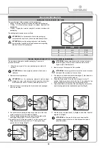
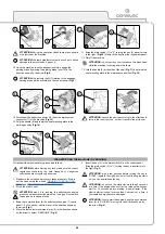
6. When the engine starts up, release the engine switch and let it
return to ON.
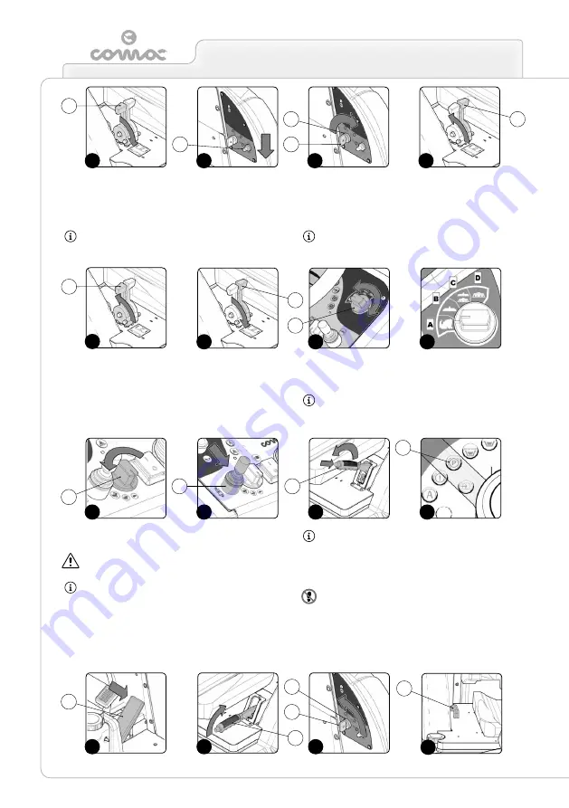
7. Bring the command lever for the endothermic engine (1) rpm to
its maximum - gradually shift the lever in the direction shown by
the arrow (
Fig.5
).
ATTENTION:
if the air command lever (5) was used to
cold-start the engine, gradually move it in the direction
shown by the arrow until it reaches the “OPEN” position
(
Fig.6
).
8. Use the i-drive adjustment switch (6) (
Fig.7
) to select the
“transfer” program (A) (
Fig.8
).
ATTENTION:
in this way, both the brush head and the
squeegee support will move to their idle position (raised
above the floor).
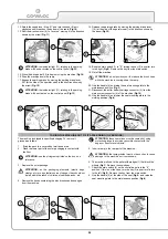
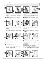
9. Select the movement speed level - e.g. “step-01” - by turning
the knob (7) (on the control panel) in the direction shown by the
arrow (
Fig.9
).
10. Select the direction in which you want to move the machine.
For example, if you want to move forwards shift the direction
selector lever (8) in the direction shown by the arrow (
Fig.10
).
11. Release the parking brake by moving the parking brake lever (9)
(at the side of the operator seat) in the direction shown by the
arrow (
Fig.11
).
ATTENTION:
the indicator light (10) relating to the engaged
parking brake will be deactivated on the control panel
(
Fig.12
).
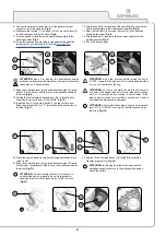
12. Press the drive pedal (11) to begin moving the machine (
Fig.13
).
13. Use a ramp to move the machine up onto the transport vehicle.
ATTENTION:
during this operation, check there are no people
or objects near the machine.
ATTENTION:
the ramp gradient must not be such as to cause
damage to the machine as it goes up.
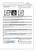
14. Once the machine is on the transport vehicle, engage the
parking brake by moving the parking brake lever (9) in the
direction shown by the arrow (
Fig.14
).
ATTENTION:
the indicator light (10) relating to the engaged
parking brake will be activated on the control panel (
Fig.12
).
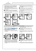
15.
Bring the main switch (4) to "0", turning the key (3) a quarter turn
to the right (
Fig.15
). Remove the key from the instrument panel.
16. Get off the machine.
ATTENTION:
do not position your foot above the brush head
while the machine is coming down the ramp.
17. Grip the handle (12) at the side of the seat (
Fig.16
), and raise
the seat mounting plate to the maintenance position (
Fig.17
).
16
12
15
14
2
3
4
1
5
1
1
2
4
4
3
3
5
8
9
7
6
5
6
7
12
13
11
10
8
9
9
10
11
Summary of Contents for ULTRA 120 B-G
Page 2: ......
Page 7: ...7 36 72 102 6 9 10 110 107 106 75 5 76 74 58 7 59 7...
Page 9: ...9 103 4 56 31 43 109 15 3 98 22 65 24 108 19 34 35 23 68 44 63 64 99...
Page 10: ...10 2 94 17 101 96 105 69 12 11 18 73 40 97 95 104 42...
Page 68: ...68 NOTES...
Page 69: ...69 NOTES...
Page 70: ...70 NOTES...
Page 71: ......


