39
PREP
ARING T
O
WORK
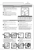
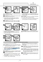
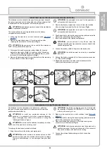
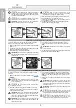
Before beginning to work, it is necessary to:
1. Make sure the recovery tank is empty. If this is not the case,
2. Check that the quantity of detergent solution in the solution
tank is right for the type of work to be carried out. If necessary,
fill the tank (for versions without CDS, read “
” and “
”; for versions with CDS, read “
” and “
FILLING THE DETERGENT CANISTER
3. Check that the squeegee rubbers are in good working condition.
If this is not the case, replace them (see “
”).
PREPARING TO WORK
4. Check that the splash guard rubbers on the brush head are in
good working condition. If this is not the case, replace them (see
“REPLACING THE BRUSH HEAD SPLASH GUARD RUBBER”).
5. Check that the disc brushes are in good working condition. If this
is not the case, replace them (see “
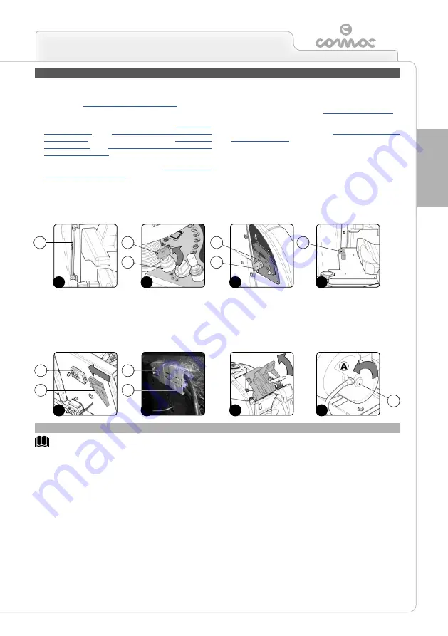
6. For versions with an endothermic engine, check the fuel level
using the indicator (1) on the right-hand side of the tank (
Fig.1
).
If necessary, fill the tank with fuel (see “
7. Check the main switch (2) on the control panel is on “0” (
Fig.2A
- B versions or
Fig.2B
- G versions). If this is not the case, turn
the key (3) a quarter of a turn to the left. Remove the key from
the instrument panel.
8. Grip the handle (4) and raise the seat mounting plate to the
maintenance position (
Fig.3
).
ATTENTION:
before starting to work, read the paragraph (in the Use and Maintenance Manual of the engine itself) listing the checks
to be carried out before use.
CHECKING THE ENDOTHERMIC ENGINE (G VERSIONS)
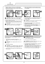
9. For battery versions, connect the battery connector (5) to the
main system connector (6) of the machine (
Fig.4A
- B versions).
10. For versions with an endothermic engine, connect the alternator
connector (7) to the general system connector (6) of the
machine (
Fig.4B
- G versions).
11.
For versions with an endothermic engine, enable the fuel flow
by closing the fuel tap (5) - move the lever (6) in the direction
shown by the arrow (
Fig.4B
- G versions).
12. Grip the handle (4) and lower the seat mounting plate to the
working position (
Fig.5
).
13. If the machine is a bi-fuel version, open the tap (8) in the
cylinder (
Fig.6
) by following the indications on it.
2A
4B
2B
5
6
3
1
4A
1
1
1
1
1
1
1
1
1
1
1
3
6
8
6
2
1
4
2
5
7
3
Summary of Contents for ULTRA 120 B-G
Page 2: ......
Page 7: ...7 36 72 102 6 9 10 110 107 106 75 5 76 74 58 7 59 7...
Page 9: ...9 103 4 56 31 43 109 15 3 98 22 65 24 108 19 34 35 23 68 44 63 64 99...
Page 10: ...10 2 94 17 101 96 105 69 12 11 18 73 40 97 95 104 42...
Page 68: ...68 NOTES...
Page 69: ...69 NOTES...
Page 70: ...70 NOTES...
Page 71: ......

