53
MAINTENANCE
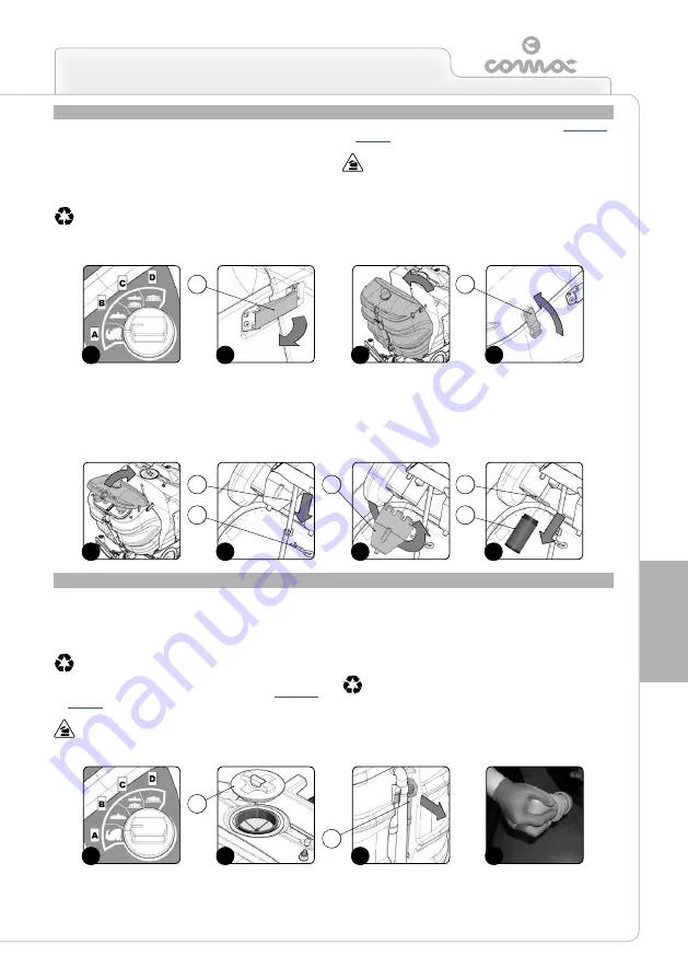
CLEANING THE VACUUM MOTOR FILTER
Careful cleaning of the vacuum motor filter guarantees a better dirty
water vacuuming capacity as well as a longer vacuum motor life.
To clean the vacuum motor filter, proceed as follows:
1. Select the i-drive program “transport” by rotating the knob to
position “A” as shown in (
Fig.1
).
2. Take the machine to the maintenance area.
ATTENTION:
the place designated for this operation must
comply with current environmental protection regulations.
3. Make sure the machine is in a safe condition (read “
”).
ATTENTION:
users are advised to always wear protective
gloves, to avoid the risk of serious injury to hands.
4. Release the recovery tank retainer hinges (1) on the side of the
tank (
Fig.2
).
5. Rotate the recovery tank until the retainer is in the maintenance
position (
Fig.3
).
6. Release the vacuum lid retainer hinges (2) on the side of the tank
(
Fig.4
).
7. Rotate the vacuum lid to the maintenance position (
Fig.5
).
8. Move the rotation retainer (3) to the locking position and insert the
safety pin (4) (
Fig.6
).
9.
Rotate the filter-cover cups (5) anti-clockwise to remove them
(
Fig.7
).
10.
Remove the vacuum motor filter retainer (6) and then the vacuum
motor filter (7) (
Fig.8
).
11.
Clean the filter with a jet of water. If necessary, remove the
impurities with a spatula.
12.
Repeat the steps from 9 to 11 for the filter of the second vacuum
motor as well.
13. Repeat the operations in reverse order to reassemble all the
parts.
DRAINING THE SOLUTION TANK
Proceed as follows to empty the solution tank:
1. Select the i-drive program “transport” by rotating the knob to
position “A” as shown in (
Fig.1
).
2. Take the machine to the maintenance area.
ATTENTION:
the place designated for this operation must
comply with current environmental protection regulations.
3. Make sure the machine is in a safe condition (read “
ATTENTION:
users are advised to always wear protective
gloves, to avoid the risk of serious injury to hands.
4. Remove the solution tank inlet cap (1) by turning it anti-clockwise
(
Fig.2
).
5. Release the solution tank drainage tube (2) (at the back of the
machine) from the retainers (
Fig.3
).
6. Bend the end of the drainage tube, so as to create a choke and
prevent the content from coming out (
Fig.4
), put the tube on the
discharge surface and gradually release the tube.
ATTENTION:
the place designated for this operation must
comply with current environmental protection regulations.
7. Repeat the operations in reverse order to reassemble all the
parts.
3
4
1
2
7
8
5
6
3
4
1
2
1
1
1
1
1
1
1
1
1
1
3
6
5
4
1
2
7
2
Summary of Contents for ULTRA 120 B-G
Page 2: ......
Page 7: ...7 36 72 102 6 9 10 110 107 106 75 5 76 74 58 7 59 7...
Page 9: ...9 103 4 56 31 43 109 15 3 98 22 65 24 108 19 34 35 23 68 44 63 64 99...
Page 10: ...10 2 94 17 101 96 105 69 12 11 18 73 40 97 95 104 42...
Page 68: ...68 NOTES...
Page 69: ...69 NOTES...
Page 70: ...70 NOTES...
Page 71: ......


