background image


12 

GENERAL SAFETY REGULATIONS 

 
The following rules must be carefully followed in order to avoid injury to the operator and damage to the machine. 


Read the labels on the machine carefully. Do not cover them for any reason and replace them immediately if they become damaged. 


The machine must be exclusively used by authorised, trained personnel. 


The machine is designed for dry use only and should not be used or kept outdoors in damp conditions. 


Disconnect from the mains/battery before performing cleaning or maintenance operations on the machine. 


If the machine is used where there is a risk of falling objects, the machine must be equipped with protections against falling objects. 


During the working of the machine, pay attention to other people and especially to children. 


The machine is not suitable for cleaning carpets. 


Do not mix different types of detergent as this may produce harmful gases. 


Do not place any liquid containers on the machine. 


The storage temperature must be between -25

C and +55

C; do not store outdoors in damp conditions. 


Conditions of use: room temperature between 0°C and 40°C with relative humidity between 30 and 95% 


Do not use the machine in an explosive atmosphere. 


Do not use the machine as a means of transport. 


Do not use acid solutions that could damage the machine and/or harm people. 


Do not vacuum inflammable liquids. 


Do not use the device to collect dangerous powders. 


In the event of a fire, use a powder extinguisher. Do not use water. 


Do not knock against shelving or scaffolding, where there is a danger of falling objects. Use protective devices (helmet). 


Adapt the speed to the adhesion conditions. 


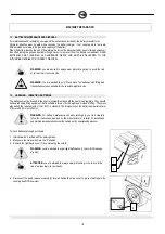
Do not use the machine on surfaces with an inclination greater than the one shown on the plate. 


When the machine is in parking mode, remove the key and engage the parking brake. 


If you notice any damage to the battery charger cable, contact a COMAC technical assistance centre immediately. 


The machine is designed to carry out the washing and drying operations simultaneously. Different operations should only be carried out in areas where 
the passage of unauthorised persons is prohibited. Signal the presence of damp floors with suitable signs. 


If the machine does not work properly, check this is not caused by failure to carry out routine maintenance. Otherwise, request the intervention of the 
COMAC technical assistance centre. 


If you need to replace any components, request the ORIGINAL spare parts from a COMAC dealer and/or Authorised Retailer. 


Use original COMAC brushes only indicated in the paragraph “CHOOSING AND USING THE BRUSHES". 


In the event of danger, activate the emergency lever (connector placed under the operator's seat) immediately. 


Before carrying out any maintenance work, switch off the machine and disconnect the battery connector. 


Restore all electrical connections after any maintenance interventions. 


Do not remove any protection devices which require the use of tools in order to be removed. 


Do not wash the machine with direct water jets or with pressurised water, nor with corrosive substances. 


After at least every 200 hours of operation, have the machine checked by a COMAC assistance centre 


To prevent scaling in the solution tank filter, do not fill the tank with detergent solution many hours before using the machine. 


Before using the machine, check that all the hatches and covers are positioned as shown in this Use and Maintenance Manual. 


Make sure the recovery tank is empty before lifting. 


When disposing of consumption materials, observe the laws and regulations in force. 


The machine does not cause harmful vibrations. 


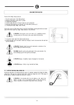
When your COMAC machine has reached the end of its long working life, dispose of the materials it contains (especially oils, batteries and electronic 
components) in an appropriate manner, and bearing in mind that the machine itself was constructed using 100% recyclable materials. 


The batteries must be removed from the machine before its disposal. 


The batteries must be disposed of in a safe manner, fully observing the laws and regulations in force. 


The machine is not suitable for use by children and persons with reduced physical, mental and sensory capabilities, or people who lack experience and 
knowledge. 


Children must be supervised to ensure they do not play with the device. 


When the machine if left unattended, engage the parking brake for safety against unintentional movements. 


Summary of Contents for ULTRA120 B

Page 1: ...USE AND MAINTENANCE MANUAL ULTRA120 B ED 05 2011 EN ORIGINAL INSTRUCTIONS Doc 10029463 Ver AA...

Page 2: ...ok symbol with an i Indicates the need to consult the instruction manual Open book symbol Used to tell the operator to read the manual before using the machine Warning symbol Carefully read the sectio...

Page 3: ...WORKING FORWARD SPEED 21 19 MOVEMENT OF THE BRUSH HEAD UNIT 22 20 INCREASING THE PRESSURE ON THE BRUSH HEAD UNIT 22 21 SOLUTION TANK 23 22 FILLING THE DETERGENT SOLUTION TANK VERSION WITHOUT CDS 23 23...

Page 4: ...HE BRUSH HEAD COVER SPLASH GUARD 43 51 WASHING THE DOSING SYSTEM VERSIONS WITH CDS 44 TROUBLESHOOTING 45 52 INSUFFICIENT WATER ON THE BRUSHES 45 53 THE SQUEEGEE DOES NOT DRY PERFECTLY 45 54 THE BRUSH...

Page 5: ...tion not absorbed by the floor The machine must only be used for this purpose Even the best machines will only work well if used correctly and kept in good working order We therefore suggest you read...

Page 6: ...670 Suction vacuum mbar 190 Rear elastic wheels mm 370 x 140 Solution tank l 280 Recovery tank l 285 Detergent tank CDS version only l 15 Steering diameter mm 3420 Machine length mm 2030 Machine heig...

Page 7: ...coustic alarm Used to indicate the acoustic alarm button Symbol denoting forwards and backwards speed selector Used on the instrument panel to indicate the speed of the forwards or backwards movements...

Page 8: ...ution in the solution tank Symbol denoting full recovery tank Used on the instrument panel to indicate the red warning light showing that the dirty water level has reached a critical level Symbol indi...

Page 9: ...cate the green warning light showing that the left hand suction motor is in operation Symbol denoting right hand suction motor Used on the instrument panel to indicate the green warning light showing...

Page 10: ...fill the solution tank Label indicating the position of the solution tank drain pipe Label indicating the position of the recovery tank drain pipe Indicates the maximum machine operating gradient Indi...

Page 11: ...se CDS system only Label with Ph value of the detergent to use CDS system only Symbol indicating regulation of water and detergent quantity CDS system only Used on the left hand panel to indicate the...

Page 12: ...of unauthorised persons is prohibited Signal the presence of damp floors with suitable signs If the machine does not work properly check this is not caused by failure to carry out routine maintenance...

Page 13: ...E paragraph 5 Keep the pallet for any future transport needs ATTENTION if the product is delivered in cardboard containers handle the packed product with suitable lifting means that comply with the le...

Page 14: ...Washing only use brushes only 10 Red warning light indicating that the motor brush head is working under pressure force 11 Red warning light indicating that there is a malfunction in the machine tract...

Page 15: ...ting that the squeegee unit has reached its operating position 22 Green warning light indicating that the left hand suction motor is in operation 23 Green warning light indicating that the right hand...

Page 16: ...ows 32 Detergent filler cap CDS version 33 Detergent level warning light CDS version The components on the front side of the machine are identified as follows 34 Step to assist getting on to machine T...

Page 17: ...ntified as follows 44 Headlights 10 TYPE OF BATTERY To power the machine it is necessary to use liquidelectrolyte lead traction batteries sealed traction batteries with gasrecombination or gel technol...

Page 18: ...G INSERTING BATTERIES The batteries must be housed in the special compartment beneath the seat mounting plate They should be handled using lifting equipment that is suitable in terms of both weight an...

Page 19: ...ries to the and poles using the supplied jumper cable 2 Connect the battery connector cable to the and poles in order to obtain a voltage of 36V at the connection terminals 3 Connect the battery conne...

Page 20: ...ycle is complete the battery connector 2 must be reconnected to the electrical system connector 1 ATTENTION Carefully read the use and maintenance instructions of the battery charger that is used for...

Page 21: ...ust remove your foot from the accelerator pedal If this service brake is working badly or if necessary activate the brake pedal 1 pushing it downwards In case of lack of oil in the braking system the...

Page 22: ...rush head unit towards the right hand side of the machine simply move the knob 1 on the instrument panel to the right to move the brush head back move the knob 1 to the left 20 INCREASING THE PRESSURE...

Page 23: ...r pipe previously modified is inserted into the quick release coupling remember to unscrew the cap 1 to allow proper air venting The solution tank has a maximum capacity of about 280 litres Add the li...

Page 24: ...ON The DS automatic dosing system is designed to work with any liquid detergent For this reason the percentage of detergent in the solution is subject to a maximum error of 5 compared with the nominal...

Page 25: ...ow should be proportional to the degree of dirt on the floor In addition remember that the time available for continuous working depends on the quantity of water in the tank for example working endura...

Page 26: ...ps of metal objects 28 ADJUSTING THE SQUEEGEE INCLINATION During operation the rear rubber must operate bent slightly backwards by about 5 mm uniformly over its whole length If it is necessary to incr...

Page 27: ...to prevent the different inclination of the bristles producing an overload on the brush motor as well as excessive vibrations ATTENTION during this operation check there are no people or objects near...

Page 28: ...hat the by pass tap is in the dosing system position 11 Turn the water flow rate adjustment knob 3 to the maximum position 12 Turn the detergent percentage adjustment knob 4 to the maximum position 13...

Page 29: ...r counter to display a different type for instance partial contact the qualified COMAC trained personnel The bottom line shows the service setting in this case there is no setting 8 The second screen...

Page 30: ...um flow of water This lever should not be used to make adjustments To obtain the correct dose to the brushes use only the knobs for adjusting the amount of water solution 10 and detergent 11 See parag...

Page 31: ...k When the brush motor overload limit is exceeded the red warning light 17 on the instrument panel begins to flash After a few seconds the motor stops and the indicator light of the brush switch goes...

Page 32: ...tank is dangerous for proper functioning of the suction motors when it is activated the suction motors are switched off and the green warning light on the button 1 goes out In this case raise the sque...

Page 33: ...l system connector from the battery connector ATTENTION Before performing any maintenance remove the keys from the panel and disconnect the battery connector of the machine 7 Disconnect the recovery t...

Page 34: ...he operations from number 14 to number 18 for the left hand side cover 18 Raise the seat support plate and connect the electrical system connector to the battery connector 19 Sit on the driver s seat...

Page 35: ...connector of the machine 37 CLEANING THE SQUEEGEE Careful cleaning of the whole suction group ensures better drying and cleaning of the floor as well as greater duration of the suction motor Proceed...

Page 36: ...of water Check the state of wear of the rear rubber If the edge of the rubber is ruined the rear rubber can be turned on all four corners If the rubbers are completely worn replace them To remove the...

Page 37: ...and turning the handwheel 2 clockwise to raise the rubbers from the ground ATTENTION Before performing any maintenance remove the keys from the panel and disconnect the battery connector of the machi...

Page 38: ...n the figure The photo shows the direction of rotation for releasing the right brush Rotate in the opposite direction for the left brush WARNING Before performing any maintenance remove the keys from...

Page 39: ...battery connector of the machine WARNING This operation must be carried out using gloves to protect against contact with dangerous solutions 7 Disconnect the suction hose from the squeegee nozzle 1 8...

Page 40: ...that the electrical system connector is disconnected from the battery connector 2 Ensure that the main switch is in the 0 position 3 Check the parking brake is engaged 4 Close the water tap 1 5 Discon...

Page 41: ...tions must be carried out using gloves to protect against contact with dangerous solutions 45 CLEANING THE SOLUTION TANK FILTER Proceed as follows for cleaning 1 Ensure that the electrical system conn...

Page 42: ...s follows 1 Ensure that the electrical system connector is disconnected from the battery connector 2 Ensure that the main switch is in the 0 position 3 Check the parking brake is engaged 4 Disconnect...

Page 43: ...the brush head cover by removing the split pins 1 5 Remove the brush head cover from its housing 6 Undo the rubber pressing blade securing nuts 2 7 Remove the rubber pressing blade 3 8 Remove the cen...

Page 44: ...e sure the recovery tank is empty otherwise empty it completely 5 Unscrew the cap of the detergent canister 1 and fill it with clean water 6 Refit the cap of the detergent tank 7 Check there is clean...

Page 45: ...SASSEMBLING THE BRUSHES and ASSEMBLING THE BRUSHES Working with over worn brushes may cause damage to the floor 2 Use a different kind of brush to the one fitted as standard For cleaning floors where...

Page 46: ...batteries are charged 61 THE AUTOMATIC WATER DETERGENT DOSING SYSTEM DOES NOT WORK The automatic water detergent dosing system has been designed with criteria of extreme sturdiness and reliability bu...

Page 47: ...parate the following materials and send them to the appropriate collection centres in accordance with the environmental hygiene regulations currently in force brushes filter electric and electronic pa...

Page 48: ...aps more easily Remember that when the bristles are worn and therefore too short they will become rigid and are no longer able to penetrate and clean deep down In this case like with overlarge bristle...

Page 49: ...1 Electromagnetic compatibility Regulations for household appliances electrical devices and similar equipment Part 1 Emission Regulation for product family EN 55014 2 Electromagnetic compatibility Reg...

Reviews: