background image

IGL-RA15 2.0.0 Global Guide

7

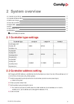
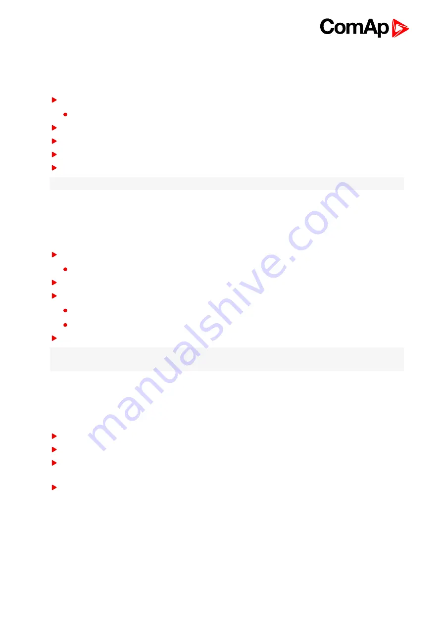
2.3 LEDs color change

Each LED color is adjusted independently of controller output settings. If controller output 1 is set as “Common

Shutdown” it doesn’t mean red LED1 color for IGL-RA15. The LEDs color can by adjust by following steps:

Switch to programming mode (Hold the

Horn reset

and

Lamp test

when unit is powering on)

Status led is yellow

Press

Horn reset

to change the LED1 color (green, yellow, red)

Press

Lamp test

to switch to the next LED color adjusting

Continue to adjust all LEDs color

After LED15 color adjusting press three times Lamp test

Note:

Signal LEDs are all adjusted to RED colors from production.

2.4 Horn timeout setting

The horn output is activated if any of red or yellow LED is on. Output is on until pressing Horn reset or horn

timeout counts down. The timeout can by set by following steps:

Switch to programming mode (Hold the

Horn reset

and

Lamp test

when unit is powering on)

Status led is yellow

Press

Lamp test

fifteen times

Set the horn timeout by pressing

Horn reset

.

The number of green luminous LEDs means timeout in 10s.

Any for disabling horn output, 1 for 10s timeout, 2 for 10s timeout, 15 for disabling horn timeout.

Press

Lamp test

two times

Note:

Note: If there is no operator action during address setting, color adjusting or timeout timeout setting, the

unit returns to normal operation without changes saving.
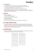
2.5 Signal LEDs

The signals LEDs are handled like binary outputs. It means all what can be configured to binary outputs can be

also configured to the LEDs of iGL-RA15.

The LED lights, if configured logical output is active on the controller

The green LED is dark, if configured logical output is not active on the controller

The yellow or red LED is dark, if configured logical output is not active on the controller and

horn reset

was

pressed.

The yellow or red LED blinks, if configured logical output is not active on the controller and

horn reset

was

still not pressed.

Summary of Contents for IGL-RA15

Page 1: ...p a s U Uranie 1612 14a 170 00 Prague 7 Czech Republic Tel 420 246 012 111 E mail info comap control com www comap control com Global Guide IGL RA15 Remote annunciator SW version 2 0 0 1 Document information 3 2 System overview 6 3 Installation and wiring 10 4 Technical data 15 ...

Page 2: ...verview 6 2 1 Controller type settings 6 2 2 Controller address setting 6 2 3 LEDs color change 7 2 4 Horn timeout setting 7 2 5 Signal LEDs 7 2 5 1 PWR LED 8 2 6 Horn 8 2 7 Lamp and horn test 8 2 8 LED labels 8 3 Installation and wiring 10 3 1 Rubber seal installation 10 3 2 Opening the IGL RA15 FPC 11 3 3 Terminals and dimensions 13 3 4 Recommended wiring 14 4 Technical data 15 ...

Page 3: ...t NT InteliLite NT or InteliLite CU IntreliDrive DCU Marine Industrial InteliDrive Mobile Logger InteliDrive Lite Lite Marine FPC IPC IPU EM IGL RA15 is equipped with a fully configurable tri color red orange green LED for intuitive operation together with high functionality Note The FPC unit does not have any buttons so all adjustment bellow needs to be adjusted by opening the cover and pressing ...

Page 4: ...le on www comap control com Security Risk Disclaimer Pay attention to the following recommendations and measures to increase the level of security of ComAp products and services Please note that possible cyber attacks cannot be fully avoided by the below mentioned recommendations and set of measures already performed by ComAp but by following them the cyber attacks can be considerably reduced and ...

Page 5: ...tion nor authentication Thus it is intended to be used only in closed private network infrastructures Avoid exposing the port TCP 502 to the public Internet 5 SNMP The SNMP protocol port UDP 161 version 1 2 is not encrypted Thus it is intended to be used only in closed private network infrastructures Avoid exposing the port UDP 161 to the public Internet 1 4 Document history Revision Number Relate...

Page 6: ...iLite IL3 CLOSED OPEN 5 6 InteliGen NT InteliSys NT InteliDrive DCU InteliLite IL3 CLOSED CLOSED user defined 2 2 Controller address setting SW changing of CAN1 address is enabled only when both jumpers are closed Any one of these addresses 1 2 or 3 4 or 5 6 or 7 8 can be set by following steps Switch to programming mode Hold the Horn reset and Lamp test when unit is powering on Status led is yell...

Page 7: ...e Hold the Horn reset and Lamp test when unit is powering on Status led is yellow Press Lamp test fifteen times Set the horn timeout by pressing Horn reset The number of green luminous LEDs means timeout in 10s Any for disabling horn output 1 for 10s timeout 2 for 10s timeout 15 for disabling horn timeout Press Lamp test two times Note Note If there is no operator action during address setting col...

Page 8: ...nd of the extended lamp test see below The horn can be silenced By pressing horn reset button or It silences automatically after adjusted time see chapter Horn timeout setting above 2 7 Lamp and horn test Pressing and holding lamp test button for less than 2s execute the basic lamp test All LEDs light up with the configured colour If the button is hold longer than 2s an extended test is started Ev...

Page 9: ...IGL RA15 2 0 0 Global Guide 9 Note Not available in FPC version EM2FPCRAEAA 6 back to System overview ...

Page 10: ...g 3 1 Rubber seal installation 10 3 2 Opening the IGL RA15 FPC 11 3 3 Terminals and dimensions 13 3 4 Recommended wiring 14 6 back to Table of contents 3 1 Rubber seal installation The correct way to install the rubber sealing is shown on the pictures below ...

Page 11: ...IGL RA15 2 0 0 Global Guide 11 3 2 Opening the IGL RA15 FPC This is just for authorized acces 1 Remove the screws 2 Bottom side ...

Page 12: ...IGL RA15 2 0 0 Global Guide 12 3 You can directly press the micro switches on PCB ...

Page 13: ...IGL RA15 2 0 0 Global Guide 13 3 3 Terminals and dimensions IGL RA15 IGL RA15 FPC ...

Page 14: ... Global Guide 14 3 4 Recommended wiring Note The shielding of the CAN bus cable has to be grounded at one point only see Technical data on page 15 for recommended CAN bus cable type 6 back to Installation and wiring ...

Page 15: ...minal impedance 120Ω Cable type twisted pair shielded CAN bus interface Following dynamic cable parameters are important especially for maximal 200 meters CAN bus length Nominal Velocity of Propagation min 75 max 4 4 ns m Wire crosscut min 0 25 mm2 Maximal attenuation at 1 MHz 2 dB 100m BELDEN see www belden com 3082A DeviceBus for Allen Bradley DeviceNet 3083A DeviceBus for Allen Bradley DeviceNe...

Reviews: