InteliMains
NT
, SW version 3.2.0
InteliMains-NT-MCB-MGCB-3.2.0-Reference Guide.pdf,
©ComAp – April 2015
19
3.2.3
Package contents
The package contains:
Controller
Screws for optional screw mounting
Terminal blocks
3.2.4
Jumper settings
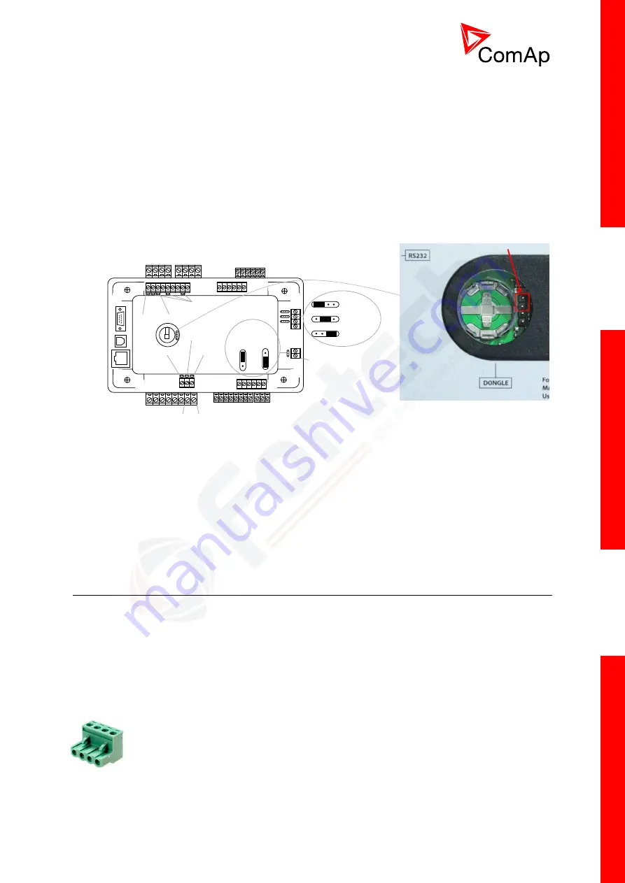
There are several jumpers available on the unit. Their location and purpose is described below.
Mains Bus
Voltage measurement
Binary inputs
1-6
120 Ω
terminators
RS232
USB
(NTC only)
Ethernet
(NTC only)
Current measurement
Mains Aux Binary outputs
1-8
Power
AI COM
Analog output
AOUT COM
AOUT -
Pull up
Pull down
Pull up
Pull down
(NTC only)
Voltage
output
0-10V
Current
output
0-20mA
Voltage input
0-5 VDC
Current input
0-25 mA
Resistance input
0-2400 Ω
120 Ω
terminator
Use boot jumper if controller is not responding to communication (e.g. due to faulty programming
sequence). Take off the rubber cover using screwdriver to acces boot jumper next to dongle slot.
Use 120
Ω
terminators at the end of CAN1, CAN2 or RS485 buses. Do not use these terminators on
units that are not terminating the bus.
Use pull up and pull down resitors on RS485 to bias the line when no device is active on the bus to
prevent noise from undriven line to be interpreted as data.
3.3
Wiring (general)
To ensure proper function:
Use grounding terminals.
Wiring for binary inputs and analog inputs must not be run with power cables.
Analog and binary inputs should use shielded cables, especially when the length is more than
3 m.
Tightening torque, allowable wire size and type, for the Field-Wiring Terminals:
For Mains(Bus) Voltage, Generator Voltage a Current terminals
o
Specified tightening torque is 0,56Nm (5,0 In-lb)
o
Use only diameter 2,0-0,5mm (12-26
AWG) conductor, rated for 90°C
minimum.
Boot jumper location


