background image


OVERVIEW 


Please  read  this  handbook  careful:  it  provides 
important  information  about  safety,  usage  and 
maintenance of our product. 

 
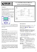
The BMR electronic regulator allows the control 
of  the  power  factor  (cos

φ

)  on  electric  networks 

by  measuring  all  the  electrical  values  such  as 
Voltage, Current, THDI(%),etc... 
Using accurate diagnosis software, the regulator 
measures only the fundamental values by 

removing the 
harmonics 
components. 


A large LCD display allows 
all  the  data  to  be  easily 

read. Regulator operation is indicated by the LEDs on the front 
panel.  All the  user operations can be performed  using the  four 
button keypad. 


INSTALLATION 

 
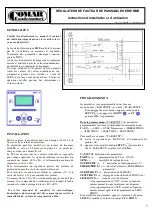
Mounting  the  regulator  in  a  cut-out  panel  (138x138mm)  by 
behind panel clamps. 
The  regulator  is  only  suitable  for  an  electrical  network  with  a 
frequency of 50/60Hz through a Current Transformer placed on 
the phase L1 and connected between the K-L terminals. 
The  C.T.  must  measure  all  the  currents  (inductive  and 
capacitive) to ensure correct operation. 
Voltage references must be connected to lines <L2>-<L3> and 
the regulator power supply on terminals <S1>-<S2>;  
for voltage supplies provide a fused supply in accordance with 
your  technical  standards.  Connect  the  aux  voltage  to  terminal 
<C>,  which  is  common  to  the  NO  relay  outputs,  and  connect 
the outputs 1 to 12 to control the banks of capacitors.


A volt-free contact on leads <C1>-<C2> is available to remote 
monitoring  an  alarm  status  or  to  control  a  cooling/fan  system: 
for  fan  control,  connect  the  included  temperature  probe  on 
<P1>-<P2> leads. 


 Be sure to know the harmonics characteristic of the network 
that must be compensated, then ensure the P.F.C. equipment 
or  capacitors  you  are  using  are  suitable  for  the  network 
characteristics  and,  if  necessary  to  avoid  any  safety  problem 
on  your  equipment,  adjust  the  THERM  THDI%  and  OVER 
THDI% parameters. 


PROGRAMMING 


The parameters can be set by two menus: a base menu 

(“PAR 

SETUP”)

 and advanced 

(“MAIN SETUP”)

.  

To navigate between the setting paramaters press the        

SETUP 

button; press        

DOWN

  or          

UP

 button to 

modify each paramater

 . 

 
In the first menu 

(“PAR SETUP”) the parameters to set are 

the minimum installation required and are shown below:  
PAR TA

SENS

OVER Temperature

THERM THD I%


OVER THD I%

SENS THD I

SENS DOWN.  

 
To access the basic (“PAR SETUP”) menu: 


 set  the  regulator  on  MANUAL  mode  by  pressing  the


MAN/AUT 

      button and disconnect all the banks 

(1)


press  and  hold  the 

SETUP 

button  until  to  read  “PAR 

SETUP” onto digital display. 

 
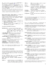
PAR SETUP parameters description: 

PAR TA 

=> 

Current Transformer ratio (eg. 1000/5).


SENS 

=> 

tolerance sensibility to the cos

φ


regulation. 

OVER TEMP

 => 

maximum operating temperature (°C). 

THERM THD I%

 =>   THD(I)% alarm value (see also the                                                                             

SENS THD I% parameter). 

OVER THD I%

 =>   instantaneous THD(I)% peak alarm 

value. 

SENS THD I%

 =>    THD(I)% alarm value time (sec.). 

SENS DOWN

 => 

alarm reset time delay : 

if set to ON, resume instantaneously the normal 
operations when the alarm ends; 
if set to OFF, resume the normal operations with a 
delay time equals to the SENS THD I% value;  
To modify these parameters, press and hold the 

SETUP

 button and change using the 

UP

 or 

DOWN


buttons. 


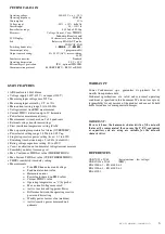
P.F.C. ELECTRONIC REGULATOR BMR series 


Installation and Operating Instructions


MU 03.14 MMM R.2 – COMAR 381011 


Summary of Contents for BMR Series

Page 1: ...i assorbimenti previsti Le uscite di comando devono essere opportu namente collegate ai rispettivi organi di intervento protetti a loro volta come tutte le parti di potenza dell impianto I contatti per il comando delle batterie sono NO con comune C interlacciato mentre il contatto di allarme è settabile NO NC FAN indipendente In base al modello sono presenti i morsetti per il collegamento seriale ...

Page 2: ...la stessa batteria di condensatori ALARM RELAY impostazione funzionamento relè di allarme NOA NCA FAN solo nel caso di impostazione del relè di allarme in modalità FAN è possibile impostare l ultima batteria del dispositivo in modalità ALARM EXTERNAL TV impostazione per la configurazione dell ingres so voltmetrico con trasformatore tensione su linea esterna se presente inserire i valori del primar...

Page 3: ... misura su 2 o 4 quadranti Impostazione dei valori primario secondario del trasformatore voltmetrico Impostazione soglia di intervento ventilazione FAN Impostazione soglia di sovratemperatura Impostazione del fattore di potenza da 0 85 Ind a 0 95 Cap Impostazione dei kvar per ogni singola batteria da 0 1 a 6000 Impostazione del tempo di riconnessione da 5 a 240s Impostazione della tensione nominal...

Page 4: ...temperature probe on P1 P2 leads Be sure to know the harmonics characteristic of the network that must be compensated then ensure the P F C equipment or capacitors you are using are suitable for the network characteristics and if necessary to avoid any safety problem on your equipment adjust the THERM THDI and OVER THDI parameters PROGRAMMING The parameters can be set by two menus a base menu PAR ...

Page 5: ...ER Active and Reactive Power measurments MAX line max values of network parameter measured 2 MAX power max network energy values measured 2 Note if the POWER FACTOR value on the display is not stable reverse the K L C T signal connections 2 All the history measurements can be reset by pressing the UP and DOWN buttons at same time The display of the parameter is 30sec after this time the regulator ...

Page 6: ...etting o Weekly power factor value medium o Active reactive power measured on 4 qudrants WARRANTY Comar Condensatori s p a guarantees its products for 12 months from purchase date Technical specifications are valid under normal operating conditions as specified in this document We do not accept any responsibility for any misuse of the product and cannot be held liable for indirect or consequential...

Page 7: ...our le contrôle des alarmes et la commande des ventilateurs pour lesquels il faudra raccorder la sonde de temperature en P1 P2 Il est trés important de connaître les caracteristiques harmoniques du réseau qui doit être compensé pour verifier la compatibilité du système de compensation utilisé PROGRAMMATION les paramètres sont programmables dans 2 menus menu de base PAR SETUP et avancé MAIN SETUP P...

Page 8: ... POWER MAX line MAX power MAIN paramètre du réseau cosφ valeur RMS de la tension valeur RMS du courant différence de puissance réactive pour obtenir le cosφ choisi THD THD total en courant valeur du courant fondamental et harmonique FAN T mesurée par la sonde en C si reliée SET cosφ Cosinus phi programmée uniquement pour consultation en mode AUTOMATIQUE modifiable en mode MANUEL à l aide des bouto...

Page 9: ...parente o Puissance active et réactive sur 4 quadrants o Maximum tension et courant mesurée o Facteur de puissance de la semaine o Puissance active réactive mesurè sur le 4 quardants GARANTIE Comar Condensatori s p a garantie ses produits 12 mois à partir de la date d achat Les caractéristiques techniques sont valables pour un usage normal du matériel Nous n acceptons aucune responsabilité en cas ...

Reviews: