background image

ENVIRONMENTS

63

Comau Robotics Product Instruction

Crd files

.

4.10.1.2.1 User text archive

It  is  a  file  containing  the  added  user  comments  to  the  error  messages,  in

Cause&Remedy

 environment. 

4.10.1.2.2 Import path

Directory path to translate PDL2 programs containing the 

IMPORT 

clause. 

4.10.1.2.3 Grammar file

This field is only used for NODAL systems. It specifies the directory of the syntax file, on

the PC. 

4.10.1.2.4 Crd files

It allows adding and removing 

.crd 

files, i.e. the ones in which looking for errors cause

and remedy from the Control Unit. Such files can be stored in whichever device on the

network, not necessarily local to the PC on which 

RoboShop 

is active.

4.10.1.3 About

Provides information about the 

RoboShop 

program (version number, release date, etc).

4.10.2 Contextual keys

None.

Summary of Contents for C5G-R1C

Page 1: ...RoboShop Program Software version 2 0 0 CR00758151_en 04 2019 11 Instruction Handbook...

Page 2: ...p A Reproduction of text and illustrations is not permitted without prior written approval by COMAU S p A COMAU S p A reserves the right to alter product specifications at any time without notice or...

Page 3: ...Definitions 10 Applicability 11 Operating modes 12 2 GENERAL DESCRIPTION 18 Introduction 18 Basic functions 19 Requirements 20 Minimum requirements 20 Suggested requirements 20 Install and activate 21...

Page 4: ...on 52 Contextual keys 54 Open File 54 I O Configuration 55 Description 55 Contextual keys 57 Settings 60 Description 60 General 60 Language 61 Default library version 61 Themes 61 Registration 62 Dire...

Page 5: ...71 MOVE ON TOP 71 Virtual State Selector 72 Virtual Enabling Device 73 Settings 73 File Transfer 74 Import path 74 Grammar file 75 Crd file 75 Translator 76 FTP Server 76 Nodes Panel 77 Details Panel...

Page 6: ...ce This symbol indicates operating procedures technical information and precautions that if ignored and or are not performed correctly could cause injuries This symbol indicates operating procedures t...

Page 7: ...l the complete manuals set for C5G R1C consists of These manuals are to be integrated with the following documents Comau Control Unit Technical Specifications Transport and installation Control Unit U...

Page 8: ...ure and to the User Interface corresponding layout changings The most meaningful described modifications are as follows Multicontrol Panel new chapter the new handling of the File System environment h...

Page 9: ...indicated in the section Applicability which should make sure that the Authorised Personnel is aware of and scrupulously follow the requirements contained in this document in addition to the general S...

Page 10: ...ined as the mechanical electrical and software integration of the Robot and Control System in any environment that requires controlled movement of Robot axes in compliance with the safety requirements...

Page 11: ...ator is the professional expert responsible for the Robot and Control System installation and startup Misuse Misuse is defined as the use of the system outside the limits specified in the Technical Do...

Page 12: ...ectly and use only adequate slings and equipment Fix the Robot to mount holder with all the provided bolts and pins tightened to the tightening torques given in the related Instruction Handbooks If pr...

Page 13: ...tions do not exceed the limits specified in the specific Instruction Handbooks The calibration operations must be carried out with utmost attention as indicated in the Instruction Handbooks of the spe...

Page 14: ...achine movements and in any case in a suitable position to avoid the risk of being trapped between the Robot and structural parts columns barriers etc or between movable parts of the Robot When progra...

Page 15: ...g module is shown in the Maintenance section of the Instruction Handbooks of the specific Robot When after the interruption of an unfinished MOVE the motion is enabled again the typical function of tr...

Page 16: ...must be concluded with the check of the correct functioning of the Robotic system Robot and Control Unit and all the safety devices executed from outside the protected area During the software loadin...

Page 17: ...ot is properly balanced and if necessary sling it correctly then remove the screws that fix the Robot to the supporting surface Remove the Robot and the Control Unit from the work area following all t...

Page 18: ...rator priviledges to be installed It should be installed on the PC running the installation program from the dedicated directory The following topics are described in this chapter Basic functions Requ...

Page 19: ...e IP addresses according to the current physical connection and without any limitations on the ports full open ports viewing files existing on the connected Control Units and the PC editing and transl...

Page 20: ...Windows PC not a virtual machine compatible with all Windows Desktop OS 64 bit currently supported by Microsoft RAM minimum size 8 GB Hardware virtualization technology extensions Intel VT x AMD V en...

Page 21: ...ge will NOT be the one for RoboShop use but only the one used during the installation phase b Accept the licence conditions and then choose the install folder for RoboShop c Choose the wished folder f...

Page 22: ...Product Instruction 22 GENERAL DESCRIPTION d A progress bar shows the operation completion status Restart the system at the end To activate RoboShop simply click the icon from either the Start Menu or...

Page 23: ...Service to obtain a full licence Act as follows a from RoboShop select Settings functionality b An alphanumeric string is provided in the Unique Identifier field belonging to the Registration area c C...

Page 24: ...Nothing to be added d Send the email e COMAU will return a licence key to be copied to the suitable field as shown in the below figure f Click Register key g A message is displayed at the end of the...

Page 25: ...User Interface includes the following areas each one allowing to access information and commands related to the System 1 Viewing Areas 2 Environments 3 Multicontrol Panel 4 Logs Bar A detailed descrip...

Page 26: ...edy if any Editor allows creating viewing and editing PDL2 programs Terminal is the direct interface with the currently selected and connected Control Unit 3D Visualization shows the 3D visualization...

Page 27: ...iewing window and a label tab containing the following information figure above name 1 name of the corresponding environment placeholder 2 allows making the panel movable or fixed Clicking the first t...

Page 28: ...Comau Robotics Product Instruction 28 VIEWING AREAS 3 2 2 Closing To close a window use the closure key available in the tab previous figure...

Page 29: ...which are necessary to properly handle the Environment itself In the shown below example the Editor environment Contextual keys are highlighted The available environments are Logger Cause Remedy Edit...

Page 30: ...ame of the Control Unit associated to a session is displayed in the session label tab as shown in the figure below The viewable Log files are the history of the events occurred on the Control Unit ass...

Page 31: ...mestamp Error Code etc simply clicking on the name of the wished column Click again to invert the order By double clicking on a Log list element the Cause Remedy environment is opened displaying the s...

Page 32: ...log Log Search Allows filtering errors by column When this command is issued the search symbol is made available in each column header figure below in order to allow searching at the column level Clic...

Page 33: ...he Count column one Severity allows matching or excluding elements by choosing a range of elements or a list of elements separated by commas based upon their error severity This window is exactly like...

Page 34: ...Comau Robotics Product Instruction 34 ENVIRONMENTS Toggle Log Colors Each click deactivates activates the Log messages background color as shown in the figures below...

Page 35: ...the find symbol RoboShop program looks for such an error in the CRD file specified in Settings Directories Crd files area Such files including all the errors and corresponding causes and remedies are...

Page 36: ...Save Comment key to confirm Such a text string is saved in the file specified in the User text archive field If deleting the existing comment is wished cancel the text string from the User Comment fie...

Page 37: ...ation in it related to the new file Type of file indicates whether a new file is wished to be created containing a PDL2 language program New PDL2 Program or empty Blank File Arm number if the new file...

Page 38: ...4 4 2 Contextual keys When the environment is open the following contestual keys are enabled New File allows creating a new file The New File window is opened exactly like when clicking the Editor ke...

Page 39: ...inning when the file end or the file beginning is reached Search Mode search modality Direction indicates whether searching is to be performed towards the file end Down or the file start Up and the fo...

Page 40: ...the figure above are as follows Toggle bookmark sets the bookmark at the current position Next bookmark moves the Editor cursor to the next bookmark Previous bookmark moves the Editor cursor to the pr...

Page 41: ...time associated to three individual Control Units is shown in the figure above La frecce presenti nell esempio mostrato nella figura sopra indicano la linea dei comandi nella finestra Terminal di cias...

Page 42: ...is environment cannot be allowed and an informational message is displayed on the screen 4 5 2 Contextual keys When the environment is open the following contestual keys are enabled Copy allows copyin...

Page 43: ...ing the mouse at the same time moves the scene floor robot and all objects in any directions long pressing the left key keeping the left key pressed and moving the mouse at the same time the floor inc...

Page 44: ...ts and Simulation 3D Scene for objects of the Nodes Panel The wished element robot or object could also be selected by CTRL clicking it in the 3D visualization area This causes its setting parameters...

Page 45: ...or Trajectory Thickness Draw Trajectory these fields are available to view the TCP trajectory of the selected robot They have the following meanings Trajectory Color this is the color for viewing the...

Page 46: ...trajectory Use the Delete Trace contextual key to cancel the currently displayed trajectory Show toolframe Show userframe select them to enable viewing respectively the Tool frame and the User frame 4...

Page 47: ...changings are immediately displayed helping the user s work 4 6 2 Contextual keys When the environment is opened the following contextual keys are enabled highlighted in red in the figure above Load...

Page 48: ...bject in the Nodes Panel Delete Trace Cancels the displayed trace of the currently selected robot trajectory Refer to par 4 6 1 1 Robot on page 44 to modify the trajectory trace settings Fit View Fits...

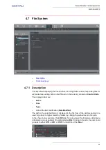
Page 49: ...he displayed data are Name Size Type date of the last modification Date Modified The path to the selected folder is displayed in the first row of the window and can be used to go back to higher hierar...

Page 50: ...s subfolders is wished use the Paste command ref Cut Copy Paste selecting the destination folder Cut Copy Paste Allows cutting copying pasting one or more elements either a folder and its subfolders o...

Page 51: ...ogs Bar as highlighted in the figure below Protect Allows protecting the selected file by means of a password Protecting folders is not available Unprotect Allows deleting the selected file protection...

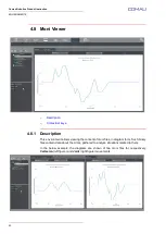
Page 52: ...ption This environment allows viewing the content of moni files in diagram form Such binary files contain data about the Arms gathered to analyze situations related to them In the below example the di...

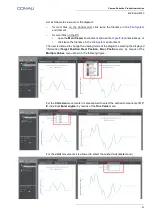
Page 53: ...click twice the filename in the File System environment The user is allowed to change the viewing mode of the diagram selecting the displayed information Target Position Real Position Error Position e...

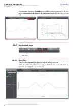
Page 54: ...the Switch from 2D charts to 3D Charts view toggle key figure below on the left 4 8 2 Contextual keys Open File 4 8 2 1 Open File This contextual key allows opening a moni log file existing on the PC...

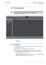
Page 55: ...displayed by the I O Configuration environment are dinamically refreshed The I O Configuration panel is composed by two areas refer to the next figure I Os list highlighted in red in the figure name...

Page 56: ...hows an example of two simultaneous I O Configuration panels Note that it is allowed to open more than one I O Configuration panels at the same time each one associated to a different Control Unit Jus...

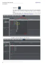
Page 57: ...ure at the beginning of current par 4 9 I O Configuration on page 55 the following contextual keys are available Add I O Device this command adds the selected I O ports associated to the wished I O de...

Page 58: ...ent view The user is allowed to select them in a list in which they are displayed by port type as shown in the figures below In the following example some I O ports are added to the ones already displ...

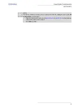
Page 59: ...NOTE Proceed as follows to remove one or more ports from the displayed ones in the I O Configuration environment open the I O ports list by means of Add I O Device or Add I O Port contextual keys uns...

Page 60: ...allows setting up the general parameters for the RoboShop program functioning figure above The setting functions are grouped as follows General Directories About 4 10 1 1 General General settings abou...

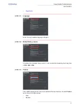
Page 61: ...le language is English 4 10 1 1 2 Default library version It indicates the translator library version to be used while translating the binary files COD VAR C5G 4 10 1 1 3 Themes Three different backgr...

Page 62: ...background by selecting it in the corresponding menu and clicking Apply key as shown in the left figure above 4 10 1 1 4 Registration The usage of this setting functionality is fully described in par...

Page 63: ...rammar file This field is only used for NODAL systems It specifies the directory of the syntax file on the PC 4 10 1 2 4 Crd files It allows adding and removing crd files i e the ones in which looking...

Page 64: ...lready stated RoboShop is able to connect to more than one Control Unit at simultaneously in the same session The Multicontrol Panel figure above is composed by Multicontrol Bar 3 1 Nodes Panel 3 2 De...

Page 65: ...a virtual Control Unit Name name to identify the being added Control Unit Url Type if adding a real Control Unit specify the IP address Url if a virtual Control Unit is to be added instead open the T...

Page 66: ...mize the new Virtual System configuration c Click the DEVICE field in the displayed page to open the menu and select the wished device from which loading the wished configuration d Click OK to confirm...

Page 67: ...on e Select arm family model auxiliary axes if any MOVE statement mode etc to configure the virtual system f Press Save key at the end to save the newly created configuration g Click OK key to confirm...

Page 68: ...hysical connection is done run RoboShop program Note that in case of Virtual Control Unit the mentioned above physical connection is not required If needed some functionality Settings can be modified...

Page 69: ...confirmation prompt When the Control Unit is disconnected the corresponding LED in the Nodes Panel becomes red 5 2 5 Teach Pendant Select the Control Unit involved in the connection with the Virtual T...

Page 70: ...al key keeps it in the opposite state if the virtual key WAS NOT pressed clicking right presses it and keeps it pressed if the virtual key WAS pressed clicking right releases it and keeps it released...

Page 71: ...board not displayed ZOOM OUT small size Each click on this key circularly changes NORMAL IN NO OUT NORMAL etc the virtual keyboard visualization as shown in the four figures above 5 2 7 2 SCREENSHOT I...

Page 72: ...tates like for the real System are Progr programming Local auto local Remote auto remote Two operation modalities are available circular at each click on the virtual selector see figure below on the l...

Page 73: ...mouse keys regardless whether right or left Each time this virtual key is clicked the current state is switched and the new state is kept 5 2 8 Settings This command allows accessing the following set...

Page 74: ...ring the files list transfer viewing operations from and to the connected PC 5 2 8 2 Import path Directory path to translate PDL2 programs containing the IMPORT clause Directly type in the Import path...

Page 75: ...L systems only It includes the PC folder in which the nodal syntax file can be read Directly type in the Grammar file field or click key as shown in the figure above to select it in the window opened...

Page 76: ...figure above and click Ok to confirm to delete it 5 2 8 5 Translator When selected this checkbox states that PDL2 programs are always offline translated even if the Control Unit is connected The path...

Page 77: ...ished folder and then clicking Select folder NET_C in case of backup and restore functionality with RoboShop acting as the Control Unit server it is allowed to use the NETx ports with x from 1 to 9 af...

Page 78: ...t associated robot objects associated to the 3D word if any The majority of such an information is related to editable settings of the corresponding Node The following figures show two examples of Det...

Page 79: ...tionalities and also from active applications if any Using the key placed on its left side as highlighted in the figure above the viewing area can be vertically enlarged reduced When the Logs Bar is r...

Page 80: ...utput Displays all messages coming from any RoboShop environments and functions and from applications if any running on the Control Unit 6 3 Search Results Displays all he results of any search operat...

Page 81: ......

Page 82: ...Made in Comau Original instructions...

Reviews: