background image

e.DO Gripper

Safety requirements, technical 
features and assembly and 
integration instructions

Requirements, technical features and instructions 
for safe installation and use of the e.DO Gripper.

CR00758190-en_00/2018.05

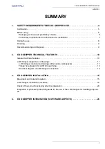
Summary of Contents for e.DO

Page 1: ...per Safety requirements technical features and assembly and integration instructions Requirements technical features and instructions for safe installation and use of the e DO Gripper CR00758190 en_00...

Page 2: ...p A Any reproduction even partial is prohibited without prior written authorization from COMAU S p A COMAU reserves the right to modify without notice the features of the product presented in this ha...

Page 3: ...eneral technical features 10 e DO Gripper diagrams and drawings 11 e DO Gripper mechanical drawings dimensions workspaces 11 Flange hole diagram for e DO Gripper fixing 13 Electrical diagram of e DO G...

Page 4: ...MENTS FOR E DO GRIPPER USE 1 SAFETY REQUIREMENTS FOR E DO GRIPPER USE In this chapter are summarized minimum safety requirements to be followed during the e DO Gripper use Certification Before using D...

Page 5: ...roperly installed and integrated on the e DO Robot it complies with the requirements of the following Community Directives DIRECTIVE 2006 42 EC OF THE EUROPEAN PARLIAMENT AND OF THE COUNCIL of 17 May...

Page 6: ...oval and preliminary checks The e DO Gripper packaging contains q ty 1 e DO Gripper q ty 1 CAN network connection cable q ty 1 e DO Gripper power supply cable q ty 2 socket hex head screws M3x8 q ty 2...

Page 7: ...obot is powered off that the related main switch is open 0 OFF position and that the power supply cable is disconnected The e DO Gripper is designed and built to be used exclusively in indoor domestic...

Page 8: ...pper see par 2 2 e DO Gripper diagrams and drawings on page 11 and Fig 1 7 Robot workspace in 6 axes configuration on page 16 and Fig 1 8 Robot workspace in 4 axes configuration on page 17 on the Robo...

Page 9: ...he Robot wrist disassemble the Robot following the assembly instructions in reverse order when present perform the disposal of the Robot e DO Gripper and various components in accordance with the law...

Page 10: ...friction factor of the neoprene covered fingers grabbing a steel object Description Feature Type 2 finger fingertips Gripper Weight 180 g Stroke Without neoprene fingertip cover 81 mm With neoprene f...

Page 11: ...ns workspaces Flange hole diagram for e DO Gripper fixing 2 2 1 e DO Gripper mechanical drawings dimensions workspaces The following drawings show the dimensions of the e DO Gripper dimensions in mm D...

Page 12: ...Comau Robotics Product Instruction 12 E DO GRIPPER TECHNICAL FEATURES Fig 2 2 Dimensions of closed e DO Gripper 25 26 79 4 39 73 14 2 50 2 50 50 32 132 5 20 50 50 50 R 3 5...

Page 13: ...truction 2 2 2 Flange hole diagram for e DO Gripper fixing The following drawing shows the diagram of holes present on the e DO Gripper flange to be used for the e DO Gripper fixing to the e DO Robot...

Page 14: ...y to be performed on the e DO Gripper electronic board PCB in order to allow its correct operation Fig 2 4 Electrical diagram of e DO Gripper connection View Description A BUS OUT connector B BUS IN c...

Page 15: ...e guards for the use of the e DO Gripper for handling purpose 3 1 Equipment and material required For e DO Gripper installation the following equipment is necessary e DO Gripper q ty 2 socket hex head...

Page 16: ...ot in calibration position vertical position as in the figure Representative figure illustrating e DO Robot in calibration position At the end of the movement shut down the e DO position the main swit...

Page 17: ...g resistor from the electronic board PCB of the last Robot joint f Insert the end with 2 connectors D CAN SUPP and CAN SIGN of the CAN network connection cable and power supply cable E included with e...

Page 18: ...upply cable E to the connector F of the last Robot joint electronic board PCB the same connector from which at step e terminating resistor was removed i Insert the end with 2 connectors D CAN SUPP and...

Page 19: ...the e DO Gripper k By means of a 2 5 mm Allen wrench fix the e DO Gripper to the last Robot joint flange using q ty 2 screws K M3x12 electronic board PCB side q ty 2 screws L M3x8 side opposite to th...

Page 20: ...g from the last Robot joint to the related connectors present on the e DO Gripper electronic board PCB as shown in the figure n Connect the 2 connectors P 2 PIN and Q 4 PIN of the power supply cable a...

Page 21: ...rd PCB as shown in the figure p Reposition the plastic protective cover of the e DO Gripper electronic board PCB no tools assembly During the repositioning of the plastic protective cover pay particul...

Page 22: ...he plastic protective cover U of the last Robot joint by using the two socket hex head screws V M3x8 After the mechanical installation of the e DO Gripper it is necessary to perform some identificatio...

Page 23: ...onnect e DO to the power supply mains and perform the power up access the related app and perform the connection via Wi Fi network through appropriate pop up windows select the Robot configuration e D...

Page 24: ...imeter protective guards installation it is also necessary to connect through the J8 connector D on Robot base an additional emergency push button C to be positioned outside the perimeter protective g...

Page 25: ...protective guards to be carried out by the User B Safety limit switch to control the correct positioning of the guard to be installed by the User C Additional emergency push button to be installed by...

Page 26: ...INTEGRATION SOFTWARE ASPECTS For the correct use of the e DO Gripper after the mechanical installation it is necessary to perform some identification and setup operations via dedicated app For furthe...

Page 27: ......

Page 28: ...Made in Comau Integration to instructions...

Reviews: