


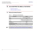


E.DO GRIPPER INSTALLATION
17
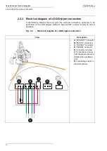
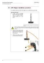
Comau Robotics Product Instruction
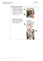
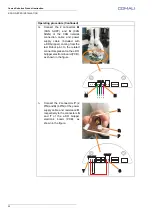
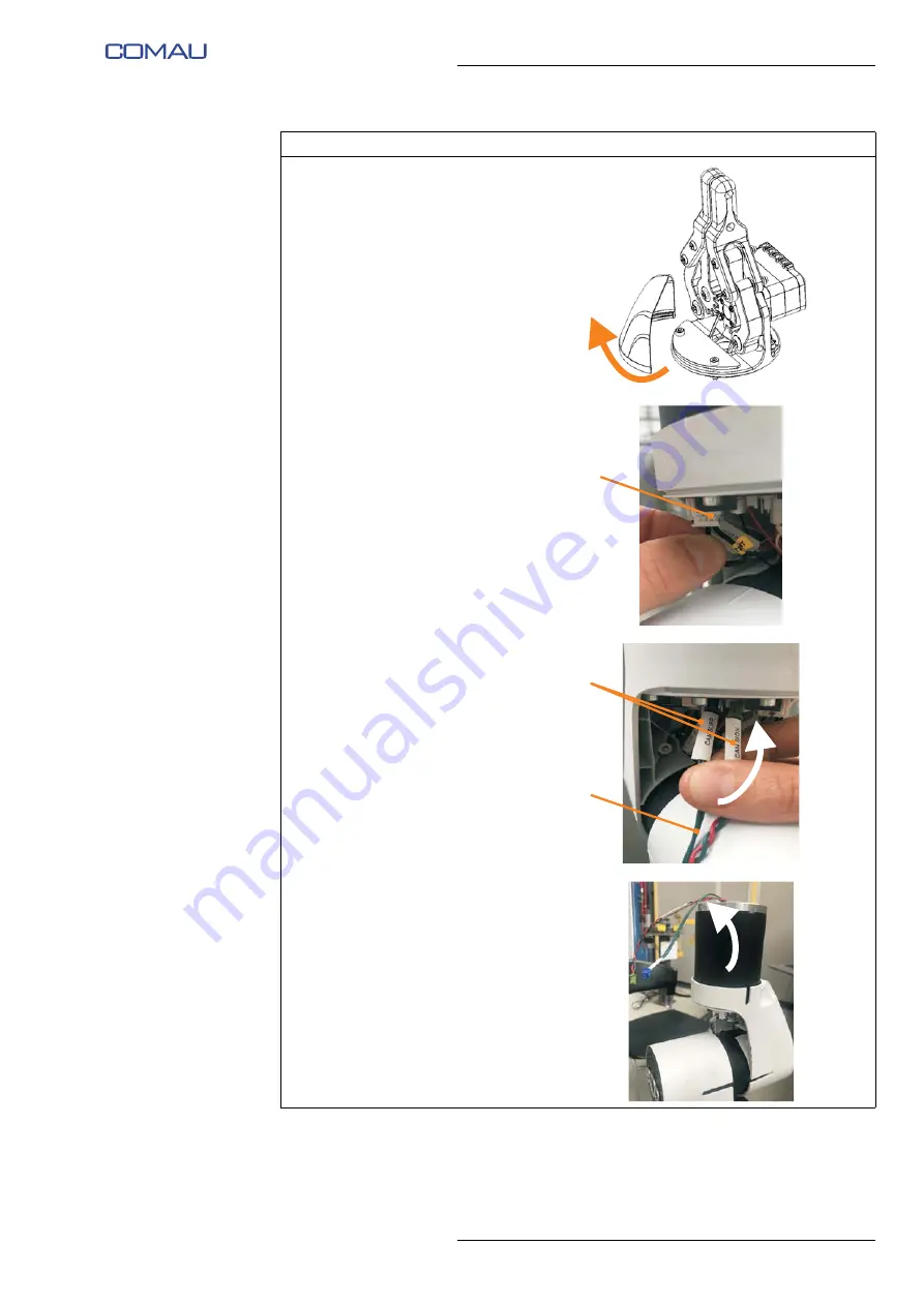
d.
Release and remove the plastic
protective cover of the e.DO
Gripper electronic board (PCB).
e.
Disconnect the CAN network
terminating resistor from the
electronic board (PCB) of the
last Robot joint.
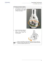
f.
Insert the end with 2 connectors
D
(CAN SUPP and CAN SIGN)
of the CAN network connection
cable and power supply cable
E
(included with e.DO Gripper)
inside the hole of the last Robot
joint, as indicated by the arrow
in the figure.
g.
Remove the two connectors
from the hole of the last Robot
joint.
Operating procedure (Continued)
C
D
E
Summary of Contents for e.DO
Page 27: ......


