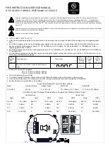
Approved Tones for EN54-3 Applications:
•(Alternating Tone) 800/1000Hz @ 2Hz Alternating Tone 44
•(Rising Tone) 500/1200Hz @ 0.26Hz (3.3s on, 0.5s off) Tone 8
•(Fainting Tone) 1200/500Hz @ 1Hz Tone 2
•(Continuous Tone) 800Hz Tone 21
•(Pulsed Tone) 660Hz (150mS on, 150mS off) Tone 31
•(Alternating Tone) 544Hz(100mS)/440Hz (400mS) Tone 5
A112
.
024
.2
(P2) @ 1m
Horizontal Sound Output Max Voltage (54 Vdc) LAFmax,T dB(A)
Horizontal Sound Output Min Voltage (11.5 Vdc) LAFmax,T dB(A)
Angle
Tone 44
Tone 8
Tone 2
Tone 21
Tone 31
Tone 5
Tone 44
Tone 8
Tone 2
Tone 21
Tone 31
Tone 5
15°
106.1
105.8
105.1
105.4
105.2
93.9
101.2
101.6
101.1
101
101.2
91
45°
105.2
107.2
106.3
104.1
98.7
101.6
101.3
102.9
102.1
100.2
94.7
99
75°
112.1
112.6
111.9
111.7
110.1
104.8
108.1
108.5
107.7
108.1
106.5
103
105°
111.9
112.5
111.7
111.7
110.2
104.8
107.9
108.4
107.6
108.1
106.4
103
135°
104.8
107.4
106.4
103.8
99.2
101.6
101.1
103.2
102.1
99.8
95.5
99
165°
105.2
105.8
105.2
105.3
105.1
93.8
100.8
101.5
100.8
100.9
102
90.8
Vertical Sound Output Max Voltage (54 Vdc) LAFmax,T dB(A)
Vertical Sound Output Min Voltage (11.5 Vdc) LAFmax,T dB(A)
Angle
Tone 44
Tone 8
Tone 2
Tone 21
Tone 31
Tone 5
Tone 44
Tone 8
Tone 2
Tone 21
Tone 31
Tone 5
15°
107.2
107.1
105.9
107.4
105.5
95.5
103.1
102.8
101.5
103.1
101.5
91.8
45°
106
109.3
107.9
104.6
100.5
103.7
102.2
105.4
103.8
100.4
96.6
99.9
75°
113.2
113.3
112.9
113
110.8
106.1
109.2
109.3
108.7
109.1
107.1
103
105°
112.9
113.1
112.7
112.8
111.4
106.1
109
108.9
108.5
108.9
107.7
103.1
135°
105.5
109.3
107.7
104.7
100.3
104.3
101.4
105.3
103.5
100.7
96.5
100.7
165°
107
106.5
105.9
106.4
105.3
95
102.6
102.1
101.5
102.2
101.1
91.2
A112
.
024
.2
(P1) @ 1m
Horizontal Sound Output Max Voltage (54 Vdc) LAFmax,T dB(A)
Horizontal Sound Output Min Voltage (11.5 Vdc) LAFmax,T dB(A)
Angle
Tone 44
Tone 8
Tone 2
Tone 21
Tone 31
Tone 5
Tone 44
Tone 8
Tone 2
Tone 21
Tone 31
Tone 5
15°
103.3
103.7
103.1
103.3
103.2
91.5
101
101.5
100.9
101
100.3
89.4
45°
103.4
104.8
104.2
101.6
96.3
99.4
101.5
102.7
101.8
99.6
94.3
97.4
75°
109.1
110.4
109.7
109.6
108.3
103.2
107.1
108.2
107.4
107.7
105.9
101.4
105°
109.9
110.2
109.6
109.7
108.6
103
107.7
108.1
107.4
107.6
105.9
101.6
135°
103.4
104.8
104
101.8
96.5
99.4
101.1
102.8
101.7
99.6
94.5
97.4
165°
103.4
103.5
103
103.3
103
91.6
101
101.4
100.8
101.1
100.2
89.4
Vertical Sound Output Max Voltage (54 Vdc) LAFmax,T dB(A)
Vertical Sound Output Min Voltage (11.5 Vdc) LAFmax,T dB(A)
Angle
Tone 44
Tone 8
Tone 2
Tone 21
Tone 31
Tone 5
Tone 44
Tone 8
Tone 2
Tone 21
Tone 31
Tone 5
15°
104.1
104.1
103.2
104.1
102.3
92.3
101.8
101.8
100.8
101.8
100
90.4
45°
103.4
106.4
105.2
101.9
96.3
100.2
101.3
104.3
103.1
99.7
94.1
98.2
75°
109.8
110.1
109.8
110.4
108.3
103.2
107.7
107.8
107.7
108.4
106.2
101.4
105°
109.1
109.9
109.5
110
108.3
102.9
106.9
107.7
107.1
107.6
105.7
101.3
135°
101.1
106.4
104.7
101.8
96.6
101
100.6
104.1
102.3
99.6
94.5
99.1
165°
103.6
103.1
102.8
103.6
102.8
91.8
101.2
100.9
100.7
101.4
99.8
89.8
Construction Product Regulation
•
A112
.
024
.2
is compliant to EN54-3:2001+A1+A2
•
Alarm devices – Sounder for use in fire detection and fire alarm systems installed in and
around buildings
•
Type 4 / 4X / 3R / 13, IP66, Independently tested to EN60529:1991, (IP33C Compliant
to EN54-3)
•
Type B Product, For Indoor & Outdoor use
•
Observe Precautions for handling electrostatic devices
•
-25°C to +55°C compliant to EN54-3
•
Cable Glands must be suitably sealed and meet minimum IP33 for EN54-3 applications
•
Storage Temperature: -40°C to +70°C
•
Maintenance – None
•
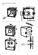
Mounting - Units can be mounted using the 2-off ø9mm holes in the mounting lugs or through the
back of the housing using the supplied gasket seal.
2821
S36282
21
Order Code: A112
.
024
.2
Voltage Range: 11.5-54Vdc
Nominal Voltage: 24Vdc
Max Current: P1: 280mA @12Vdc;
P2: 430mA @24Vdc
DP-2821-CPR-0108


