background image

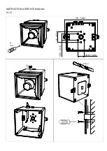
INSTRUCTION & SERVICE MANUAL 

A112


• 

All models are approved for use as Audible Signal Appliance 

for use as General Signaling: UL464A & CSA C22.2 No 205-17 

• 

Type 4 / 4X / 3R / 13, IP66

• 

-40°C to +66°C / -40°C to +151°F 

General Signaling Canada: 

A112

.

024

.2

:  -40°C  to  +55°C  /  -40°F  to  +131°F  

A112

.

230

.7

: -40°C to +40°C / -40°F to +104°F  

• 

To maintain Ingress Protection, cable entries must be fitted with suitably rated cable glands or stopping plugs

• 

EOL Monitoring (DC Only): End of Line Devices may be fitted between the +ve & -ve terminals of the PCBA. Please ensure that the device

legs meet the wire size range stated for the connection terminals and are fitted correctly in order to avoid a short. Refer to the compatible 

control panel specification for EOL device values and ratings. 

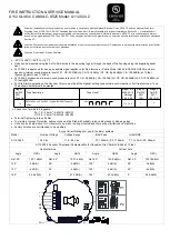
Model 

Nominal 

Voltage 

Voltage 

Range 

P1 Nominal 

Operating 

Current

#


P1 Max Operat 

ing RMS


P2 Nominal 

Operating 

Current

#


P2 Max Operating 

RMS


A112

.

024

.2


12V dc  

11.5 - 54V ac  

280mA 

280mA  

376mA 

430mA 

24V dc  

225mA 

430mA 

48V dc 

122mA 

223mA 

115V ac  

100- 240V ac 

50/60Hz 

100mA 

101mA 

A112

.

230

.7


173mA 

181mA 

230V ac 

65mA 

105mA 

*Max Operating current for worst

-

case input voltage; Nominal current at nominal voltage and Tone 44

The units have been tested and approved to DNVGL-CG-0339 & EN54-3:2014 

incl. A1:2019 for the installation on ships in the following locations: 
Temperature: 

A, B, C & D (Machinery spaces, control rooms,  

accommodation, bridge, inside cubicles,  

desks, etc..., pump rooms, holds, rooms with no  

heating, Open deck, masts) 

Humidity: 

A & B (All locations) 

Vibration: 

A (Bulkheads, Beams, Deck, Bridge) 

EMC: 

A & B (All locations Including Bridge & open deck) 

Enclosure: 

A, B & C (Control rooms, accommodation, bridge,  

engine room, open deck masts, below floor plates in 

engine room) 

The units comply with Solas 74 Chapter II-2, Regulation 7 & Chapter X, 

Regulation 3 for installation on ships in the following locations: 
Temperature: 

D (Location -25° to +70°C) 

Vibration:   

A (General Applications) 

EMC: 

B (Bridge & Open Deck Zone) 

Enclosure:   

IP56, Salt mist 

Summary of Contents for 961478441

Page 1: ...tention Installation must be carried out by an electrician in compliance with the latest codes and regulations Attention L installation doit tre effectu e par un lectricien conform ment aux derniers c...

Page 2: ...P1 P2 L N E C S2 S3 S2 S1 AC P1 P2 Default S2 Tone 1 Default S1 Tone 44 ON 1 OFF 0 AC DC See D221 95 001 DC Only see D221 06 001 H2 H1 ve switching Default H2 H1 ve switching Link W1 See D221 06 005...

Page 3: ...INSTRUCTION SERVICE MANUAL A112 4x 1Nm 190 7 48in 35 9 1 41in 35 9 1 41in 61 2 40in 20mm...

Page 4: ...8 Tone 2 Tone 21 Tone 31 Tone 5 Tone 44 Tone 8 Tone 2 Tone 21 Tone 31 Tone 5 15 103 3 103 7 103 1 103 3 103 2 91 5 101 101 5 100 9 101 100 3 89 4 45 103 4 104 8 104 2 101 6 96 3 99 4 101 5 102 7 101 8...

Page 5: ...Operating RMS A112 024 2 12V dc 11 5 54V ac 280mA 280mA 376mA 430mA 24V dc 225mA 430mA 48V dc 122mA 223mA 115V ac 100 240V ac 50 60Hz 100mA 101mA A112 230 7 173mA 181mA 230V ac 65mA 105mA Max Operati...

Page 6: ...1 0 1 0 0 1 1 0 1 0 0 0 0 1 1 0 0 1 0 1 1 0 0 0 1 1 1 0 0 1 1 1 1 0 0 0 0 0 0 1 0 1 0 0 0 1 0 0 1 0 0 1 0 1 1 0 0 1 0 0 0 1 0 1 0 1 0 1 0 1 0 0 1 1 0 1 0 1 1 1 0 1 0 1 1 0 1 1 0 0 0 1 1 1 0 0 1 1 1 1...

Page 7: ...5mA P2 1164mA P1 140mA P2 286mA A112 024 2 Sounder Directional Characteristics for Canadian Fire CAN ULC S525 at 10 feet Horizontal Axis Vertical Axis Angle OSPL Angle OSPL Angle OSPL Angle OSPL Ref 9...

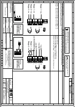
Page 8: ...CTION NTS 1 3 OPTIONAL LINE MONITORING RESISTOR CUSTOMER SUPPLIED 14V MAX SYSTEM 120 MIN 2W MIN OR 1K MIN 0 5W MIN 28V MAX SYSTEM 470 MIN 2W MIN OR 2 4K MIN 0 5W MIN RECOMMENDED MINIMUM VALUES R1 Stag...

Page 9: ...mon ve IN Common ve OUT Stage 1 ve OUT Stage 3 ve Stage 1 ve IN H2 H1 Stage 1 ve Stage 1 ve Stage 2 ve Stage 2 ve OF 2 3 R1 S2 S3 R1 S2 R2 OPTIONAL LINE MONITORING RESISTOR CUSTOMER SUPPLIED 14V MAX S...

Page 10: ...SARD R N POTTS A112 A121 DC SOUNDER WIRING DIAGRAMS NTS Stage 1 ve Stage 1 ve Stage 2 ve Stage 2 ve OF 3 3 R1 R1 S2 R2 Two Stage Configuration Config 4 Line Stage Monitoring Use suitable monitoring re...

Page 11: ...A112 A121 AC WIRING DIAGRAMS NTS 1 SWITCHES FOR STAGE OPERATION CUSTOMER SUPPLIED 1 Earth Earth Stage 2 Stage 3 Common Live IN Live OUT Neutral IN Neutral OUT Earth Stage 1 Stage 2 Common N N L L E N...

Page 12: ......

Reviews: