USER MANUAL FOR COMFLEX-6900
ENU STATUS : 1-0-0
Copyright - refer to title page
Page 37
4 COMMISSIONING
4.1 PRE-COMMISSIONING TASKS
After equipment installation, perform the following steps before equipment powering and commissioning,
check that the expected voltage, current, and power levels do not violate any ratings. Double check all
connections including ground before applying power. Do not manipulate circuits or make changes when
power is applied:
Visually inspect the power connection within the equipment. Ensure that all cables are correctly and
securely connected, including power cables, grounding wires, RF cables and optical cables.
Check grounding connection and verify that the ground resistanc
e is less than 5Ω.
Connect the equipment to the PC.
Power on MU and RU.
Monitor the initialization of the MU and RU though the LEDs on the panel. Refer to detailed LEDs
information in the next section.
4.2 LED INDICATORS
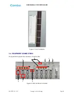
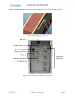
Diagnostic LEDs are located on the MU front panel and RU bottorm panel; each indicates the status of a
particular function:
Table 7: MU LED Indications
LED Indicator
Normal Status
Indication
PWR
Steady green
Power indicator. If LED is off, it indicates the system has
no power.
RUN
Flashing green
(1 time/sec)
MU operation indicator. After initialization (1~2 minutes),
the LED should flash at once per sec. (When upgrade
firmware, LED will flash rapidly)
ALM
OFF
Alarm indicator. If LED is RED, there is an alarm.
OP
Steady green
Located on Fiber Optical Unit (FOU), it is an indicator for
receive optical power. If LED is off, it indicates the
receiving optical power is less than -10dBm.
Table 8: RU LED Indications
LED Indicator
Normal Status
Indication
COMM.
Blinking green
(1 time/sec)
BLINKING GREEN - Flashes (rate of flash per second)
for the duration of 1 minute upon communication
initialization
RAPID/NO FLASH - Indicates communication fault
RUN
Off
OFF
– Normal operation
RED - Fault
ALM
Off
Alarm indicator. If LED is RED, there is an alarm.
LED Indicator
Normal Status
Indication

