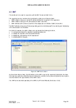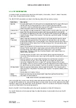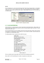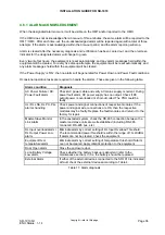
INSTALLATION GUIDE FOR SR-1910
SR-1910 QI
Copyright - refer to title page
Page 25
ENU Status : 1-1-1
3.5.5 PHYSICAL CONNECTION TO OMT PC
The local commissioning and management of the SR-1910 can be achieved by local connection of the
equipment to the OMT PC.
To establish the connection between the OMT and the equipment, connect the RS-232 port located on the
bottom of the enclosure of the Master Unit or Slave Unit to the serial port of the OMT PC using the supplied
RS-232 cable. This completes local connection between the OMT PC and the equipment.
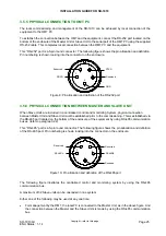
This “RS-232” port is a 5-pin round connector. The following figure shows the pin allocation and definition.
Pin numbering is shown looking into the connector on the enclosure.
Reserved
CRXD
CTXD
GND
1
2
3
5
4
Reserved
Figure 9: Pin allocation and definition of the RS-232 port
3.5.6 PHYSICAL CONNECTION BETWEEN MASTER AND SLAVE UNIT
When Slave Units are included in a centralized control and monitoring System, physical connection
between Master Unit and Slave Unit must be established prior to the commissioning. This is established via
the RS-485 port located on the bottom of the enclosure of the equipment by using RS-485 communication
buses. (refer to paragraph 2.2)
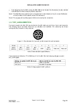
This “RS-485” port is a 5-pin round connector. The following figure shows the pin allocation and definition
of the RS-485 port. Pin numbering is shown looking into the connector on the enclosure.
Reserved
RS485/A
3
1
2
4
5
Reserved
RS485/B
Reserved
Figure 10: Pin allocation and definition of the RS-485 port
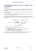
The following figure illustrates the centralized control and monitoring system by using the RS-485
communication bus.
A maximum of 32 Slave units can be cascaded in one system.
Either one of the following may be used at any one time:
•
For management by the OMT, the local PC is connected to the Master Unit, as in the above figure. And
the connection between the Master and the Slave Units is made by using the RS-485 communication
bus.


