INSTALLATION GUIDE FOR SR-1910
SR-1910 QI
Copyright - refer to title page
Page 26
ENU Status : 1-1-1
•
For management by the OMC, ensure the SIM /UIM card is inserted into the wireless modem installed
in the Master Unit before powering ON the equipment.
Note1: The RS-485 communication bus is not supplied by Comba. Details on how to connect the Master
Unit to the Slave Unit is outside scope of this document.
Note2: The equipment should be powered off when connecting the connectors.
3.5.7 EXT_ALM CONNECTION
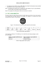
Four alarm inputs to the SR-1910 are provided on the EXT_ALM port, which is a 7-pin round connector.
The following figure and table shows the pin allocation and definition. Pin numbering are shown
looking-into the connector on the enclosure.
7
6
3
5
4
1
2
Figure 11: Pins allocation for 7-pin EXT_ALM connector for external alarms
Pin No
1
2
3
4
5
6
7
Alarm
definition
EXT.
Alarm 1
EXT.
Alarm 2
EXT.
Alarm 3
GND
EXT.
Alarm 4
Reserved Reserved
Table 3: External alarm signal definition
These signals are defined as “TTL/CMOS level”. For the SR-1910, the following voltages are valid
EXT_ALM signals:
Voltage as applied to EXT Alarm pin
Alarm condition as seen by SR-1910
0V to 1.5V
Alarm recognized
3.5V to 5V
No Alarm recognized
Table 4: Voltage applied to EXT_ALM pin


