INSTALLATION GUIDE FOR SR-1910
SR-1910 QI
Copyright - refer to title page
Page 28
ENU Status : 1-1-1
Wireline Modem
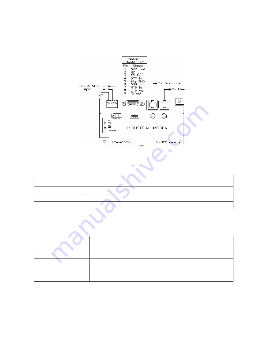
For the equipment variant equipped with wireline modem, the modem provides the link for data and alarm
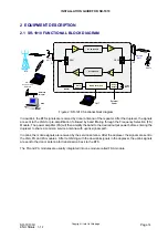
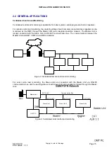
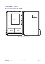
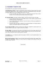
code. The following figure shows the diagram of the wireline modem.
Figure 13: Diagram of wireline modem
RS232 and VDC Input ports are pre-wired to the equipment. The following table provides the definitions of
the main ports on the modem.
To Line
1
Connects the modem to the Public Switched Telephone Network (PSTN)
by using an RJ-11 cable.
To Telephone
Connects to a telephone directly by using an RJ-11 cable (optional).
RS232 Port
It is a ‘DB9’ port, which connects to the DB9 port on the distribution board.
VDC Input
Connects to 10 - 30 VDC supply.
Table 5: Wireline modem connectors
On the modem, there are five status LEDs colored in red. Shown below are the definitions of these LEDs.
CD (Carrier detect)
The modem has detected a carrier on the phone line (a remote modem
has been detected).
TR (Data Terminal Ready) The PC (or SIXNET Station) has established a connection to the modem
and is ready for transmission.
RD (Receive Data)
Flashes as data is received from the phone line.
TD (Transmit Data)
Flashes as data is sent out the phone line.
Power
ON when power is present.
Table 6: Wireline status LEDs
End of section
1
Comba does NOT provide the RJ-11 cable. So the connection of the wireline modem to the PSTN network is outside the scope of
this document.

