INSTALLATION GUIDE FOR SR-1910
SR-1910 QI
Copyright - refer to title page
Page 32
ENU Status : 1-1-1
4.5 DESCRIPTION OF PARAMETERS
The parameters being described are applicable to SR-1910 product variants C1 and C2. The output power
differs for different product variant when connected to the OMT.
Upon successful connection between the OMT and the equipment, equipment parameters can be read
and/or set.
Parameters include: Common Information, RF Information, Alarm Information and Properties Information.
4.5.1 COMMON INFORMATION
It includes: System Info and Auto-Read. Different parameter has different interface, which can be displayed
by clicking the nodes in [Equipment Information Tree] in the left of the OMT screen.
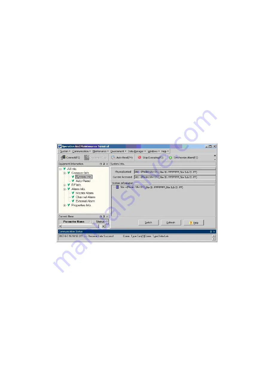
Click the [System Information] node in the [Equipment Information Tree] area to view the system
information, which will be displayed on the right side of the OMT screen, in which the equipment model
name, equipment site ID and site sub ID will be shown.
Figure 15: System information window
Clicking on [Auto Read] node a window will be shown on the right side of the OMT main screen, in which
user can define which parameters to be read automatically and the time interval for each read operation
(Ref 0.6.3).
Switch between Master and Slave Unit
In the cascaded system, with the master unit connected, in the [System Info.] window, select the Site (e.g.,
Site 01) where the slave unit is located, and select the [Switch] button, it will successfully switch from the
master unit to the selected slave unit, indicated by a message “Online Ok”. At this stage, user can read and
set slave unit parameters. Use the same way to switch from slave to master unit.
In general, the master and slave units share the same parameters. But when the slave unit is not integrated
with modem, the [Comm Config] parameter is not available for it.


