INSTALLATION GUIDE FOR SR-1910
SR-1910 QI
Copyright - refer to title page
Page 4
ENU Status : 1-1-1
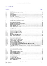
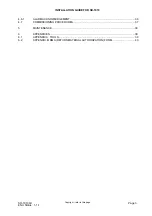
0.3 INDEX TO FIGURES AND TABLES
Figure 1: Front, side and bottom views of the SR-1910 enclosure............................................................ 13
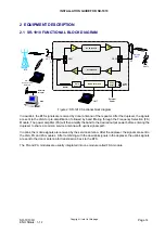
Figure 2: SR-1910 functional block diagram.............................................................................................. 14
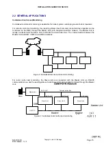
Figure 3: Centralized remote control and monitoring ................................................................................ 15
Figure 4: Centralized local control and monitoring .................................................................................... 15
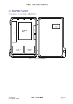
Figure 5: Layout of the SR-1910................................................................................................................ 16
Figure 6: Wall mounting overview.............................................................................................................. 21
Figure 7: Wall mounting overview.............................................................................................................. 22
Figure 8: Equipment connectors ................................................................................................................ 23
Figure 9: Pin allocation and definition of the RS-232 port ......................................................................... 25
Figure 10: Pin allocation and definition of the RS-485 port ....................................................................... 25
Figure 11: Pins allocation for 7-pin EXT_ALM connector for external alarms........................................... 26
Figure 12: Wireless modem ....................................................................................................................... 27
Figure 13: Diagram of wireline modem...................................................................................................... 28
Figure 14: OMT main screen ..................................................................................................................... 30
Figure 15: System information window...................................................................................................... 32
Figure 16: Switch configuration window .................................................................................................... 34
Table 1: SR-1910 variants ......................................................................................................................... 12
Table 2: The SR-1910 connectors............................................................................................................. 23
Table 3: External alarm signal definition.................................................................................................... 26
Table 4: Voltage applied to EXT_ALM pin................................................................................................. 26
Table 5: Wireline modem connectors ........................................................................................................ 28
Table 6: Wireline status LEDs.................................................................................................................... 28
Table 7: MCU LEDs ................................................................................................................................... 29
Table 8: SR-1910 RF parameters description ........................................................................................... 33
Table 9: Alarm list ...................................................................................................................................... 34
Table 10: Properties Info descriptions ....................................................................................................... 35
Table 11: Alarm diagnosis ......................................................................................................................... 36
Table 12: Commissioning procedures ....................................................................................................... 37


