background image

USER MANUAL FOR MBDA-200S


ENU STATUS : 1-0-0 

Copyright - refer to title page 

Page 13 


2.3  EQUIPMENT CONSTITUTION 

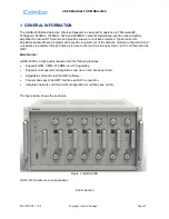
mBDA consists of the following parts: 
 

Table 1: mBDA Components 

Module 

Description 

mBDA-RACK 

There are total 7 slots in the main chassis, where six slots for RF Units and 
Combiner Units, first slot is for Power & Monitoring Unit. 

mBDA-PMU 

Power & Monitoring Unit (PMU) converts the input voltage into stable DC to supply 
power for each RF module and provides monitor control. 

mBDA-RFU 

RF Unit processes UL/DL signal and amplifies the signal for coverage. 


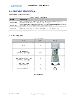
2.4  KIT OF PART 

Table 2: KOP 

Item 

Qty 

Image 

Rack 


RF Unit (RFU) 

(

Packing separately

1~2 


Power & Monitoring Unit (PMU) 

(

Packing separately


Power Supply Cable 

(13 Feet 1 inch) 


Communication Cable 


End of Section 
Summary of Contents for mBDA

Page 1: ...B BA AN ND D S SE EL LE EC CT TI IV VE E W WI IR RE EL LE ES SS S R RE EP PE EA AT TE ER R USER MANUAL MBDA 200S QE 1 0 0 Comba Telecom Ltd mBDA 200S...

Page 2: ...Comba International Comba All rights reserved The information contained herein is confidential and the property of Comba and is supplied without liability for errors or omissions No part may be repro...

Page 3: ...AYOUT 12 2 3 EQUIPMENT CONSTITUTION 13 2 4 KIT OF PART 13 3 INSTALLATION 14 3 1 WARNINGS AND ALERTS 14 3 2 SITE PLANNING CONSIDERATIONS 15 3 3 INSTALLATION PROCEDURES 16 3 4 EQUIPMENT CONNECTORS 26 3...

Page 4: ...ER MANUAL FOR MBDA 200S ENU STATUS 1 0 0 Copyright refer to title page Page 4 7 APPENDICES 50 7 1 APPENDIX A TOOLS FOR INSTALLATION AND MAINTENANCE 50 7 2 APPENDIX B RMA RETURN MATERIAL AUTHORIZATION...

Page 5: ...ommissiong Flow Chart 30 Figure 25 Input IP Address 32 Figure 26 Input Domain Name 32 Figure 27 Input User Name and Password 32 Figure 28 Web GUI Main Screen 33 Figure 29 Devices Sceen 33 Figure 30 Po...

Page 6: ...Setting 46 Figure 56 Commissioning Procedure DL Output Power Setting Screen 47 Figure 57 Commissioning Procedure DL Output Power Setting 47 Figure 58 DL Output Power Over Exceed 48 Figure 59 Commissio...

Page 7: ...USER MANUAL FOR MBDA 200S ENU STATUS 1 0 0 Copyright refer to title page Page 7 0 3 HISTORY Change No ENU Details Of Change 1 1 0 0 This user manual first created in Aug 2014...

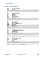
Page 8: ...oise Amplifier MCU Main Control Unit MT Mobile Terminal MTBF Mean Time Between Failures MBDA Master Unit NC Normally Closed NF Noise Figure NO Normally Open OMC Operation Maintenance Center OMT Operat...

Page 9: ...party responsible for compliance Such modifications could void the user s authority to operate the equipment This device complies with Part 22 and 24 of the FCC Rules Operation is subject to the follo...

Page 10: ...requirements of the network Remote configuration and surveillance is possible through Comba s remote control and monitoring system via PC or Ethernet to the OMC Main feature mBDA 200S is a high qualit...

Page 11: ...peater After the duplexer the signals are sent to the LNA module for pre amplification and digital RF integrated module for digital filtering and frequency conversion Then the DL signals will be sent...

Page 12: ...USER MANUAL FOR MBDA 200S ENU STATUS 1 0 0 Copyright refer to title page Page 12 2 2 EQUIPMENT LAYOUT 58 6 81 4 482 58 6 26 1 436 485 6 439 265 2 Figure 3 Layout of mBDA...

Page 13: ...mbiner Units first slot is for Power Monitoring Unit mBDA PMU Power Monitoring Unit PMU converts the input voltage into stable DC to supply power for each RF module and provides monitor control mBDA R...

Page 14: ...ems involving adverse weather extreme temperatures wet corrosive or dirty conditions flammable or explosive atmospheres the system must be suitably installed to prevent danger Protective Earthing For...

Page 15: ...d unrestricted air flow The installation location for the system should be well ventilated The equipment has been designed to operate at the temperature range and humidity level as stated in the produ...

Page 16: ...mizing the length and number of RF connections Ensure the equipment will be operated within the stated environment refer to datasheet Where appropriate confirm available of suitably terminated grade o...

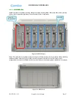
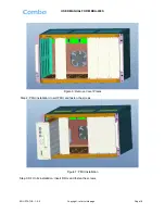
Page 17: ...d separately Follow the steps below to assemble Figure 4 mBDA Screen Step1 The rack with cover plates is shown as Figure 5 Please remove the cover plates before installing related modules Show as Figu...

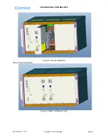
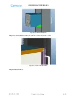
Page 18: ...U STATUS 1 0 0 Copyright refer to title page Page 18 Figure 6 Remove Cover Plates Step 2 PMU installation Insert PMU and fasten the screws Figure 7 PMU Installation Step 3 RF Units installation Insert...

Page 19: ...USER MANUAL FOR MBDA 200S ENU STATUS 1 0 0 Copyright refer to title page Page 19 Figure 8 RF Unit Installation Step 4 Finish Installation Figure 9 mBDA Installation Finish...

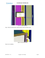
Page 20: ...mal equipment cabinet the installation procedures are shown as below Step 1 Make sure the equipment cabinet is available with pallet and the pallet is fixed steadily Equipment Cabinet nuts screws and...

Page 21: ...DA 200S ENU STATUS 1 0 0 Copyright refer to title page Page 21 Figure 11 mBDA Installation Step 3 Attach the mBDA onto the cabinet with the recommended rack screws Figure 12 Secure the Screws Step 4 F...

Page 22: ...TING mBDA can also be installed in 19 rack mounting the installation procedures are shown as below Step 1 Install right angle bracket and left angle bracket on back of the mounting rack 19 Rack nuts s...

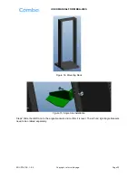
Page 23: ...1 0 0 Copyright refer to title page Page 23 Figure 14 Mounting Rack Figure 15 Angle Iron Installation Step2 Slide the mBDA on to the angle brackets and confirm it is level The left and right angle br...

Page 24: ...DA 200S ENU STATUS 1 0 0 Copyright refer to title page Page 24 Figure 16 mBDA Installation Step 3 Attach the mBDA onto the rack with the recommended rack screws Figure 17 Secure the Enclosure Step 4 F...

Page 25: ...USER MANUAL FOR MBDA 200S ENU STATUS 1 0 0 Copyright refer to title page Page 25 Figure 18 Finish Installaiton...

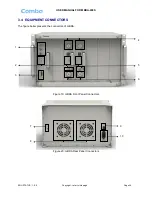
Page 26: ...ENU STATUS 1 0 0 Copyright refer to title page Page 26 3 4 EQUIPMENT CONNECTORS The figure below presents the connectors of mBDA Figure 19 mBDA Front Panel Connectors Figure 20 mBDA Rear Panel Connec...

Page 27: ...CPL Output coupler port 40dB QMA female 6 MT RF output port Mini Din female 7 Grounding connector 8 FAN Fan inside 9 POWER Power switch 10 AC100 240V AC power supply connector 3 5 EQUIPMENT CONNECTION...

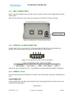
Page 28: ...cation and definition Pin numbering are shown looking into the connector on the enclosure 1 2 3 4 Figure 23 Pins Allocation for EXT_ALM Port for mBDA Table 4 Pin Definition of EXT_ALM Port for mBDA Pi...

Page 29: ...ounding wires and RF cables Check grounding connection and verify that the ground resistance is less than 5 Connect the equipment to the PC Power on equipment Monitor the initialization of the equipme...

Page 30: ...dure is shown below Connect and inquiry status Set channel No Input power detection and adjust the direction of Donor Antenna Output power confirmation Drive test and adjust the direction of Service A...

Page 31: ...Monitoring Parameters Select the equipment controlled and monitored parameters If the external devices are connected to the equipment for management please enable in the External Alarm Info Interface...

Page 32: ...e to set up a physical connection Step 2 Open browser browser IE7 0 IE8 0 Chrome or Firefox suggest disply resolution is 1024 768 input Web GUI IP address 192 168 8 101 click Enter Figure 25 Input IP...

Page 33: ...log in the Web GUI main screen will appear We take dual bands products for example Figure 28 Web GUI Main Screen On Comba Web GUI Home Screen there are four Menu bars Devices Commissioning Firmware a...

Page 34: ...USER MANUAL FOR MBDA 200S ENU STATUS 1 0 0 Copyright refer to title page Page 34 PMU Main Management Screen Figure 30 Power Monitoring Unit RF Unit Management Screen Figure 31 RF Unit...

Page 35: ...put power or reflected power is still over the threshold PA Service Status will turn to Recovery again If PA output power or reflected power is still over the threshold after six times of PA Recovery...

Page 36: ...ious one Follow steps shown in below figure to upgrade firmware Figure 34 Firmware Screen Upgrade Step 4 After clicking a window will pop up and click Figure 35 Firmware Screen Pop up Window 1 Step 5...

Page 37: ...e Page 37 Figure 36 Firmware Screen Swap 5 2 4 MANAGEMENT Other parameters can be configured on Management Screen Figure 37 Management Sceen There are nine function bars list in the left side of the M...

Page 38: ...below sub band alarm enable ATT value RF switch DL output power and so on Import and Export can help users quickly configure mBDA parameters For example if one mBDA finished configuration users can e...

Page 39: ...be set correctly according to the location IP of remote connection If more than one equipment is connected to the public network through the same router the router s local IP CANNOT be set as 192 168...

Page 40: ...re 42 Modify Password Note Username cannot be modified Device Reset Figure 43 Management Device Reset Note If users click all the parameter and alarm will set to factory default value Device Reset pro...

Page 41: ...t Figure 44 Management PA Reset Note PA will be turned off by software when PA output power or VSWR reflected power is exceed the threshold Users need to reset PA after debugging Device Info Figure 45...

Page 42: ...lation Note This Step is the same as step3 of Commissioning Users can check isolation again by clicking Check button Report Figure 47 Management Report Note Click Create to create report The report ca...

Page 43: ...G PROCEDURE To complete the installation and commissioning users need to follow the steps below Step 1 Click Menu bar Commissioning on home screen a work flow will show up Figure 48 Commissioning Proc...

Page 44: ...service antennas before proceeding to step 4 Step 4 Click to enter to Isolation Detection Screen shown as Figure 52 Select a frequency band RFU that need to commission Click to start Isolation Detecti...

Page 45: ...STATUS 1 0 0 Copyright refer to title page Page 45 Figure 51 Commissioning Procedure Isolation Detective Figure 52 Commissioning Procedure Isolation Detective Confirm Figure 53 Commissioning Procedur...

Page 46: ...0 Copyright refer to title page Page 46 Figure 54 Commissioning Procedure Isolation Detection Finish Step 5 RF Setting Screen for setting subband bandwidths and switchs Figure 55 Commissioning Proced...

Page 47: ...L output power setting after finishing subband bandwidths and switchs setting Figure 56 Commissioning Procedure DL Output Power Setting Screen Figure 57 Commissioning Procedure DL Output Power Setting...

Page 48: ...STATUS 1 0 0 Copyright refer to title page Page 48 Figure 58 DL Output Power Over Exceed Step 7 Click to commission other RFUs parameters Click to finish the commissioning Figure 59 Commissioning Pro...

Page 49: ...ent operation status can be observed remotely through OMC Periodic inspection of the repeater equipment s is recommended the recommended tasks includes Inspect and record operation status and output p...

Page 50: ...ENDIX A TOOLS FOR INSTALLATION AND MAINTENANCE The following tools not included in package are required for installation or routine maintenance Power Drill for wall mount Adjustable Wrench 0 31 inch 0...

Page 51: ...FOR MBDA 200S ENU STATUS 1 0 0 Copyright refer to title page Page 51 7 2 APPENDIX B RMA RETURN MATERIAL AUTHORIZATION End of Section End of Document FOR NAM OFFICE EMAIL PLEASE INSERT support us comba...

Page 52: ...USER MANUAL FOR MBDA 200S ENU STATUS 1 0 0 Copyright refer to title page Page 52...

Reviews: