USER MANUAL FOR MBDA-200S
ENU STATUS : 1-0-0
Copyright - refer to title page
Page 28
3.5.3 mBDA CONNECTIONS
Step1: Connect the mBDA DT port to the RF Source downlink, and then connect mBDA MT port with RF
Source uplink.
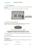
Step 2: Connect the power cable to the power supply port (100-240VAC, 1Amp maximmum).
Figure 22: mBDA Power Connection (Rear Panel)
3.5.4 EXTERNAL ALARM CONNECTION
For EXT-ALM, this is a 4-pin connector. The following figure and table show the pin allocation and
definition. Pin numbering are shown looking-into the connector on the enclosure.
1
2
3
4
Figure 23:
Pins Allocation for “EXT_ALM” Port for mBDA
Table 4
: Pin Definition of “EXT_ALM” Port for mBDA
Pin number
1
2
3
4
Alarm definition
EXT. Alarm 1
GND
EXT. Alarm 2
GND
Note: Users need to configure Ext Alm 1~2 on WEB GUI to realize External Alarm (Refer to Chapter 5).
3.5.5 CONNECT TO PC
The local commissioning and management for mBDA is achieved through connecting to the WEB based
GUI.
Connect mBDA to PC
Connect mBDA
“OMT” port (RJ45) to the RJ45 port of PC with supplied Ethernet cable to achieve local
monitoring and management.
End of Section
Power Connector


