background image

ONU User Manual 

Page 39 


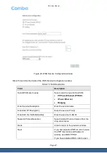
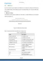
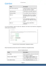
Figure 29: Virtual Servers Configuration window 

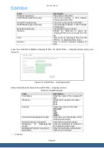
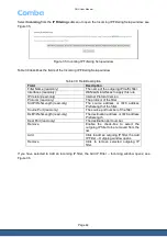
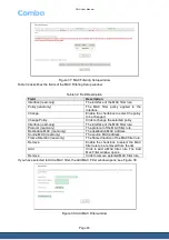
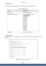
Table 24 describes the fields of the Virtual Servers Configuration window. 

Table 24: Field Description 

Field 

Description 

Use Interface 

Select Virtual Server User 
Interface. 

Service Name 

Select one of the following: 


Select a Service 


Custom Service 

If you selected 

Custom 

Service

 ,allow you to enter virtual 

server’s name. 

Service IP Address 

Enter Virtual Server IP Address 

External Port Start 

External Port Start of the virtual 
server 

External Port End 

External Port End of the virtual 
server 

Protocol   

The protocol of the virtual server. 

Internal Port Start 

Internal Port Start of the virtual 
server 

Internal Port End 

Internal Port End of the virtual 
server 

Summary of Contents for ML-HGU-F04P2T0W1N01

Page 1: ...ONU ONU HGU F04P2T0W2N01 Introduction QI 1 0 0 Comba Telecom Ltd...

Page 2: ...ch vests in Comba International Comba All rights reserved The information contained herein is confidential and the property of Comba and is supplied without liability for errors or omissions No part m...

Page 3: ...OPOLOGY 12 1 7 ONU SERVICE DESCRIPTION 13 2 CONFIGURATION IN WEB GRAPHIC USER INTERFACE 14 2 1 LOGIN 14 2 1 1 Management IP settings 14 2 1 2 Procedure 14 2 2 DEVICE INFO 15 2 2 1 Summary 16 2 2 2 WAN...

Page 4: ...ND TABLES Figure 1 ONU Appearance 8 Figure 2 ONU back and side panel 9 Figure 3 ONU back and side panel 11 Figure 4 ONU back and side panel 12 Figure 5 ONU services distribution 13 Figure 6 Logging wi...

Page 5: ...ccess Time Restriction window 47 Figure 40 Access Time Restriction configuration window 48 Figure 41 URL Filter window 49 Figure 42 URL Filter Add window 50 Figure 43 QoS Queue Management Configuratio...

Page 6: ...gure 71 Voice SIP Advanced setting window 80 Figure 72 Voice SIP Advanced configuration window 81 Figure 73 Voice SIP Debug setting window 84 Figure 74 Voice SIP Debug configuration window 84 Figure 7...

Page 7: ...ONU User Manual Page 7 0 3 HISTORY Change No ENU Details Of Change 1 1 0 0 Initial document released in...

Page 8: ...Powerful service access capability Device adopts single mode fiber wavelength division multiplexing WDM IP data service transmission distance is 20km 1 x SC APC optical PON port 4 x 10 100BASE T Ether...

Page 9: ...default by keep pushing for 3 seconds USB To connect USB flash disk mobile hardware Power Power adapter interface On Off Power switch 1 4 TECHNICAL SPECIFICATION Table 2 ONU technical specification P...

Page 10: ...Link distance 100m WiFi Support IEEE 802 11bn gn 2 x 2 MIMO Network Network Protocol Support IPv4 IPv6 VLAN Comply with IEEE 802 1q Support transparent bridging 802 1q bridging QoS 4 queue priorities...

Page 11: ...ONU User Manual Page 11 Figure 3 ONU back and side panel...

Page 12: ...ation and accounting services and providing the services etc a VoIP server For example SIP server b IPTV multi cast server c PPPoE DHCP server Aggregation layer Aggregation server works as a bridge be...

Page 13: ...rface 1 7 ONU SERVICE DESCRIPTION Figure 5 ONU services distribution Multi service access ONU supports 3 types of services simultaneously Internet VoIP and IPTV a Based on the designing of entire netw...

Page 14: ...to a web enabled PC and turned on Note For first time configuration connect the Ethernet cable from your computer to the LAN port on the ONU The default settings assign an IP subnet and an IP address...

Page 15: ...then click OK Note The default admin username is admin and the default admin password is admin 4 After logging in the device home info page appears as in figure 7 Figure 7 Device Info 2 2 DEVICE INFO...

Page 16: ...ONU technical specification Field Description Board ID read only The board ID of the gateway Build Timestamp read only Compile time of the software Software Version read only The current version of th...

Page 17: ...s a list of the configured interfaces of the WAN Click WAN in the Device Info menu to open the WAN Info window see Figure 9 Figure 9 WAN Info Table 4 Field Description Field Description Interface read...

Page 18: ...Address read only The IPv6 address of the WAN service 2 2 3 Statistics The Statistics menu contains statistical information about the LAN WAN service and Optical Select Statistics in the Device Info...

Page 19: ...smitted Errors Errs transmitted Packets dropped Drops Reset Statistics Click to reset the statistics table WAN Service The WAN window displays the statistics for the information received and transmitt...

Page 20: ...cs Click to reset the statistics table 2 2 4 Route The Route window displays the route status information Click Route in the Device Info menu to open the Route window see Figure 12 Figure 12 Route win...

Page 21: ...en the DHCP window see Figure 13 Figure 13 Route window Table 8 Field Description Field Description Hostname read only The hostname of the device connected to the LAN port MAC Address read only The HW...

Page 22: ...rface menu to open the EPON Interface Configuration window see Figure 14 Figure 14 EPON Interface Configuration window Table 9 Field Description Field Description Interface Name read only The number o...

Page 23: ...escription Field Description Back Click to return to the previous window Apply Save Click to save changes 3 ETH Interface The ETH WAN Interface Configuration window enables you to add delete or modify...

Page 24: ...N Configuration for details Remove Click to remove a selected connection 4 ETH WAN Configuration If you have selected to add or modify an ETH interface connection the ETH WAN Configuration window open...

Page 25: ...indow Table 13 describes the fields of the WAN Service Setup window Table 13 Field Description Field Description Interface read only The WAN service Description read only The WAN service mode Type rea...

Page 26: ...WAN service see Figure 19 Figure 19 WAN Service Interface Configuration window Table 14 describes the fields of the WAN Service Interface Configuration window Table 14 Field Description Field Descrip...

Page 27: ...et PPPoE IP over Ethernet Bridging Enter Service Description Enter the service name Enter 802 1P Priority 0 7 Enter the service Priority Enter 802 1Q VLAN ID 0 4094 Enter the service VLAN ID Network P...

Page 28: ...vice type the PPP Username and Password window opens see Figure 21 Figure 21 PPP Username and Password window Table 16 describes the fields of the PPP Username and Password window Table 16 Field Descr...

Page 29: ...an amount of time between 1 and 4320 minutes that the connection can have no traffic before it automatically disconnects PPP IP extension Enable to allow the gateway to use PPPoE to get the WAN IP an...

Page 30: ...to support IGMP proxy Back Click to return to previous window Next Click to configure the default gateway See Routing Default Gateway for details 4 WAN IP Settings If you have selected IP over Ethern...

Page 31: ...for information Use the following Static IP address Select to use a specified static IP address for the WAN IP WAN IP Address Enter a static IP address WAN Subnet Mask Enter a subnet mask WAN gateway...

Page 32: ...6 DNS Server Configuration If you have configured the default gateway and clicked Next the DNS Server Configuration window opens see Figure 24 Figure 24 DNS Server Configuration window Table19 describ...

Page 33: ...ice and clicked Next the WAN Setup Summary window opens see Figure 25 Figure 25 WAN Setup Summary window Table 20 describes the fields of the WAN Setup Summary window Table 20 Field Description Field...

Page 34: ...and MAC address The default IP address is 192 168 1 1 and the subnet mask is 255 255 255 0 The user can configure these addresses through the LAN Setup window Select LAN from the Advanced Setup menu t...

Page 35: ...ynamic IP address range Start IP Address If you have enabled DHCP server enter a start IP address End IP Address If you have enabled DHCP server enter an end IP address Leased Time hour Enter a time i...

Page 36: ...Enable to configure a secondary IP address and subnet mask for the LAN interface Enter the second IP Address and Subnet Mask of the LAN interface in the fields Apply Save Click to save changes 1 IPv6...

Page 37: ...ver Leased Time hour Enter DHCPv6 leased time Enable RADVD Enable Disable RADVD Prefix Enter the prefix Preferred Life Time hour Enter preferred life time Valid Life Time hour Enter valid life time En...

Page 38: ...erver Internal Port Start read only Internal Port Start of the virtual server Internal Port End read only Internal Port End of the virtual server Server IP Address read only The Virtual Servers IP Add...
Page 39: ...one of the following Select a Service Custom Service If you selected Custom Service allow you to enter virtual server s name Service IP Address Enter Virtual Server IP Address External Port Start Ext...
Page 40: ...on Trigger Protocol read only The Port Trigger Protocol Trigger Port Range Start read only The Port Trigger port range Trigger Port Range End read only The Port Trigger port range Open Protocol read o...

Page 41: ...Interface Application Name Select one of the following Select an application Custom application If you selected Custom application allow you to enter application s name Trigger Port Start Enter start...

Page 42: ...e Security submenu 1 IP filtering IP filtering allows you to configure the outgoing and incoming IP filter settings Select IP Filtering from the Security menu to open the IP Filtering submenu Outgoing...

Page 43: ...f you have selected to Add an outgoing IP filter the Add IP Filter Outgoing window opens see Figure 34 Figure 34 Add IP Filter Outgoing window Table 29 describes the fields of the Add IP Filter Outgoi...

Page 44: ...Version Protocol read only The protocol of the filter SrcIP PrefixLength read only The source address or IPv6 address PrefixLength of the filter Source Port read only The source port number of the fil...

Page 45: ...ngth Source Port port or port port Enter the source port number Destination IP Address prefix length Enter the destination IP address or IPv6 address prefix length Destination Port port or port port E...

Page 46: ...cy Interface read only The interface of the MAC filter rule Protocol read only The protocol of the MAC filter rule Destination MAC read only The destination MAC address Source MAC read only The source...

Page 47: ...to save changes 2 3 6 Parental Control The Parental Control menu enables you to configure time restrictions and setup URL filters Select Parental Control from the Advanced Setup menu to open the Paren...

Page 48: ...n window opens Remove Click to remove selected time restriction If you have selected to Add an access time restriction the Access Time Restriction configuration window opens see Figure 40 Figure 40 Ac...

Page 49: ...to open the URL Filter window see Figure 41 Figure 41 URL Filter window Table 36 describes the fields of the URL Filter window Table 36 Field Description Field Description URL List Type Select Exclud...

Page 50: ...iption URL Address Enter the URL address Port Number Enter the port number Apply Save Click to apply and save the URL to the filter list 2 3 7 Quality of Service Quality of Service enables you to conf...

Page 51: ...le 38 Field Description Field Description Enable QoS Enable to apply QoS Select Default DSCP Mark Select the default DSCP mark Apply Save Click to save changes 1 Queue Config Select QoS Queue from the...

Page 52: ...e selected queue s from the QoS Queue list If you have selected to Add Queue the QoS Queue configuration window opens see Figure 45 Figure 45 QoS Queue Configuration window Table 40 describes the fiel...

Page 53: ...cation window Table 41 Field descriptions Field Description Add Network Traffic Class Rule Traffic Class Name Enter the traffic class name Rule Order Select the order of the rule Note The only availab...

Page 54: ...n MAC Mask Enter the destination MAC mask for the QoS rule Specify Classification Results Specify Class Queue Required Select a classification queue Mark Differentiated Service Code Point DSCP Select...

Page 55: ...he Default Gateway window Table 42 Field descriptions Field Description Selected Default Gateway Interfaces Select WAN Interface as default Gateway Availabl Available Routed WAN Interfaces Available R...

Page 56: ...The selected gateway IP address Interface read only The selected interface metric In the routing protocol algorithm to calculate the complete get a variable s value Remove Enable the check box to sele...

Page 57: ...changes 3 Policy Routing Select Policy Routing in the Routing menu to open the Policy Routing Setting window see Figure 50 Figure 50 Policy Routing Setting window Table 45 describes the fields of the...

Page 58: ...able 46 describes the fields of the Policy Routing Setup window Table 46 Field descriptions Field Description Policy Name Enter a name for the policy Physical LAN Port Select a LAN port Source IP Ente...

Page 59: ...terfaces Available DNS WAN Interfaces list Use the following Static DNS IP Address Use Static DNS function Primary DNS Server Enter the Primary DNS Server Secondary DNS Server Enter the Secondary DNS...

Page 60: ...Field descriptions Field Description Hostname The user whom the Hostname restriction is applied Availabl Username The user whom the Username restriction is applied Service Default display the dyndns...

Page 61: ...the Dyndns Hostname Interface Select the WAN Service Username Enter the Dyndns Username Password Enter the Dyndns password Apply Save Click to save changes 2 3 10 UPnP The UPnP Configuration window a...

Page 62: ...xy Configuration window Table 51 describes the fields of the DNS Proxy Configuration window Table 51 Field descriptions Field Description Enable DNS Proxy Enable to turn on DNS Proxy Host name of the...

Page 63: ...Total Space read only Storage Devices total space Used Space read only Storage Devices used space 2 3 13 Interface Grouping The Interface Group window allows you to configuration multiple ports to PVC...

Page 64: ...roup LAN Interfaces The lan interfaces of the interface group DHCP Vendor IDs DHCP Vendor IDs of the interface group Add Click to add a interface group the Add Interface Grouping A maximum 16 entries...

Page 65: ...g DHCP Vendor IDs Enter the DHCP vendor ID string Save Apply Click to save changes 2 3 14 IP Tunnel Select IP Tunnel from the Advanced Setup menu to open the IP Tunnel submenu 1 IPv6inIPv4 Select IPv6...

Page 66: ...the IP Tunneling 6in4 tunnel to be removed from the list Add Click to add a service the IP Tunneling 6in4 Tunnel Configuration window opens Remove Click to remove a selected service If you click Add...

Page 67: ...v4 address Save Apply Click to save changes 2 IPv4inIPv6 Select IPv4inIPv6 from the IP Tunnel submenu to open the IP Tunneling 4in6 Tunnel Configuration window see Figure 62 Figure 62 IP Tunneling 4in...

Page 68: ...of the IP Tunneling 4in6 Tunnel Configuration window will open see Figure 63 Figure 63 IP Tunneling 4in6 Tunnel Configuration window Table 58 describes the fields of the IP Tunneling 4in6 Tunnel Confi...

Page 69: ...Connection Remote Gateway read only The Remote Gateway of IPSec Tunnel Mode Connection Local Addresses read only The Local Addresses of IPSec Tunnel Mode Connection Remote Addresses read only The Remo...

Page 70: ...escription IPSec Connection Name Enter the IPSec Connection name Tunnel Mode Select one tunnel mode of the IPSec Tunnel Mode Connection ESP AH Availabl Remote IPSec Gateway Address IPv4 address in dot...

Page 71: ...Select Key Exchange Method Auto IKE Manual Authentication Method Select Authentication Method Pre Shared Key Certificate X 509 Pre Shared Key Enter the pre shared key Perfect Forward Secrecy Select Di...

Page 72: ...idge Restrict Select one bridge restrict of following Enabled Enabled Scan Disabled If select bridge restrict Enable Scan the remote bridges MAC address will display If select Disable bridge restrict...

Page 73: ...d submenu see Figure 67 Figure 67 Wireless Advanced window Table 62 describes the fields of the Wireless Advanced window Table 62 Field descriptions Field Description Band Band of wireless 2 4GHZ Chan...

Page 74: ...ess Off Auto OBSS Co Existance Disable Enable OBSS Co Existance of wireless RX Chain Power Save Disable Enable RX Chain Power Save of wireless RX Chain Power Save Quiet Time If enable RX Chain Power S...

Page 75: ...of wireless Beacon Interval Beacon Interval of wireless Global Max Clients The maximum clients allowed to connect XPress Technology Disable Enable XPress Technology Transmit Power Transmit Power of w...

Page 76: ...t MAC address Associated Connection status Authorized Authority status SSID Wireless SSID Interface The name of the wireless interface Apply Save Click to save changes 2 5 VOICE 2 5 1 SIP Basic Settin...

Page 77: ...Name Select the type of Bound Interface from the list box LAN Any_WAN Start SIP client Start the Vodsl task Stop SIP client Stop the Vodsl task Restore default setting To restore default setting Apply...

Page 78: ...ocale selection Select a country from this list box The call progress tones will be defined to match the standard call progress tones of the county that you selected SIP domain name Set the SIP domain...

Page 79: ...he information it receives in those requests into the location service for the domain it handles SIP Registrar Enter the SIP Registrar SIP Registrar port Enter the SIP Registrar port Account Enable En...

Page 80: ...igure advance features of the voip application Select SIP Advanced Setting from the Voice menu to open the SIP Advanced Setting submenu seeFigure 71 Figure 71 Voice SIP Advanced setting window Table 6...

Page 81: ...anced Setting window Table 67 Field descriptions Field Description Call Waiting Enable Disable call waiting service Call forwarding number The target phone number the incoming call will be forwarded t...

Page 82: ...get number which used by warm line function Anonymous call blocking If enabled all incoming anonymous calls will be blocked Anonymous calling If enabled the identification will not be displayed on the...

Page 83: ...p time Raising the SIP packet priority in relation to other traffic reduces the delay DSCP for RTP Set Differentiated services codepoint for RTP package Dtmf Relay setting Dual tone Multifrequency Rel...

Page 84: ...level Error Notice Debug Start SIP client Start the Vodsl task Stop SIP client Stop the Vodsl task Apply Click to apply changes Service Provider 0 Click to open the Voice SIP Debug configuration windo...

Page 85: ...the VAD support Ingress gain Select the Ingress gain Egress gain Select the Egress gain Start SIP client Start the Vodsl task Stop SIP client Stop the Vodsl task Apply Click to apply changes 2 6 DIAGN...

Page 86: ...MANAGEMENT 2 7 1 Settings The Settings windows enable you to backup update and restore the settings of the ONU Select Settings in the Management menu to open the Settings submenu Backup The Backup win...

Page 87: ...fault Settings window enables you to restore the factory defaults of the ONU Warning Restoring the default settings will erase all previous settings Select Restore Default from the Settings submenu to...

Page 88: ...ure the system log The Configuration window opens If you clicked View System Log in the System Log window the System Log information window opens see Figure 80 Figure 80 System Log information window...

Page 89: ...System Log window the Configuration window opens see Figure 81 Note Configuring the system log should be done with assistance from your ISP Figure 81 Configuration window Table 74 describes the field...

Page 90: ...n Apply Save Click to save changes 2 7 3 Security Log The System Log windows enable you view the security log of the ONU Select Security Log in the Management menu to open the Security Log window see...

Page 91: ...ear and reset here Right click here Save a Security Log file If you clicked View in the Security Log window the Security Log information window opens see Figure 9 8 Figure 83 Security Log information...

Page 92: ...ONU User Manual Page 92 APPENDIX B RMA RETURN MATERIAL AUTHORIZATION FORM End of Document...

Page 93: ...USER MANUAL for ML OMTXXX2SS1 Page 10...

Reviews: