USER MANUAL FOR COMFLEX-4500 5W
ENU STATUS : 1-0-0
Copyright - refer to title page
Page 23
Step 5:
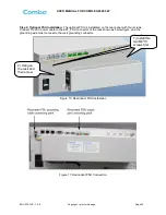
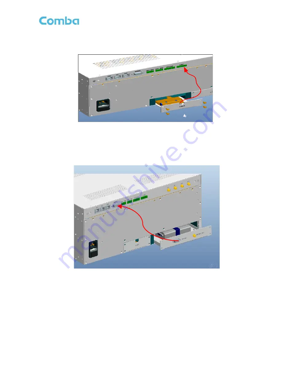
Optional Li-Battery unit installation:
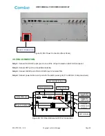
Access the optional Li-Battery unit into the slot on the rear
panel and screw it using four M3*8 screws. Connect LI_BAT cable of the unit to the LI_BAT connector of
the rack shown as below figure, and screw it.
Figure 12: Optional Li-Battery Unit Installation
Step 6:
Optional modem unit installation:
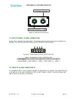
Instert the SIM card into the modem abutment before
installation. Access the optional modem unit into the slot on the rear panel and screw. Connect MODEM
connector with MODEM connector of the rack with communication cable in the packing kit. Screw it using
four M3*8 screws and installate the antenna on the MODEM ANT port of optional modem unit.
Figure 13: Optional Modem Unit Installation
3.3.5
MU IN 19” RACK MOUNTING
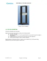
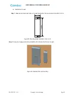
MU is an indoor type device; the installation procedures are shown as below:
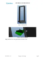
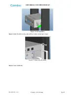
Step 1:
Install right angle bracket and left angle bracket on back of the mounting rack. (Rack nuts and
screws are not provided.) Use rack nuts and screws as recommended by rack manufacturer
.


