USER MANUAL FOR COMFLEX-4500 5W
ENU STATUS : 1-0-0
Copyright - refer to title page
Page 35
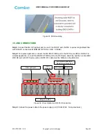
Figure 31: RU Grounding
3.5.4 MU CONNECTIONS
Step1:
Connect the MU OP (optical) port to one of the RU OP port. (NOTE: requires Single Mode fiber
with SC/APC connectors; MAXIMUM OPTICAL LOSS = 6.5dBo)
Step 2:
For duplex application, connect the MU RFU TX/RX port to the RF Source (BTS or BDA). For
simplex application, connect the MU RFU TX/RX port to the RF Source downlink, and then connect MU
RFU RX port with RF Source uplink. (NOTE: RF cable must be N-Male on the MU side)
Local commissioning &
Remote monitoring port
BTS Alarm
Reserved
Fiber optic port
RF port, to BTS
LED
indicator
Figure 32: Fiber Optical and RF Port Connection
Step 3:
Connect the power cable to the power supply port (100-240VAC, 1Amp maximum).

