USER MANUAL FOR COMFLEX-4500 5W
ENU STATUS : 1-0-0
Copyright - refer to title page
Page 37
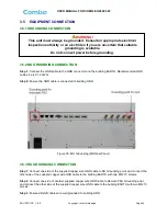
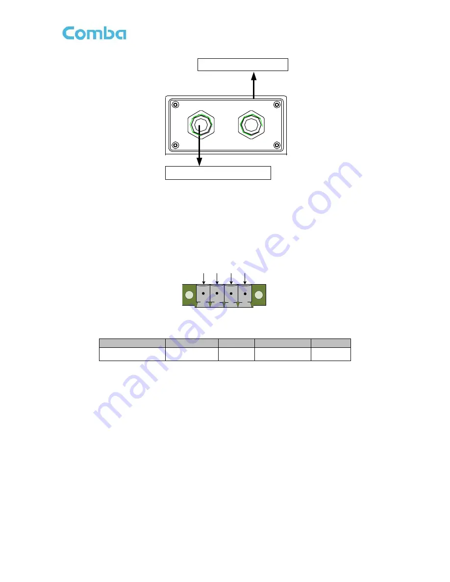
DC power connection
–
to RU
DC 28V
AC 100V-240V
50Hz/60Hz
AC Power connection
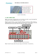
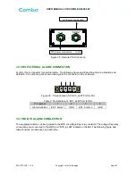
Figure 35: Remote PSU Connction
3.5.6 RU EXTERNAL ALARM CONNECTION
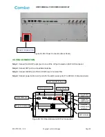
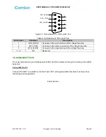
For RU, this is connector for external alarm. The following figure and table show the pin allocation and
definition. Pin numbering are shown looking-into the connector on the enclosure.
1
2
3
4
Figure 36:
Pins Allocation for “EXT_ALM” Port for RU
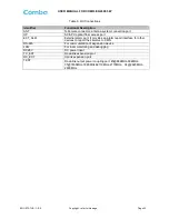
Table 7
: Pin Definition of “EXT_ALM” Port for RU
Pin number
1
2
3
4
Alarm definition
EXT. Alarm 1
GND
EXT. Alarm 2
GND
3.5.7 MU BTS ALARM CONNECTION
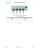
The equipment alarms can be signaled to the BTS via voltage-free relay contacts. The voltage-free relay
connections are connected to the DB-9 port
“BTS_ALAM” located on the MU. The following figure and
table show the pin allocation and definition.


