background image

INSTALLATION GUIDE FOR RX-1839 


ENU STATUS : 1-0-0 

Copyright - refer to title page 

Page 17 


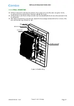
3.3.4  WALL MOUNTING


  Drill four holes on the wall using the position of four holes on the mounting rack as a guide. Fix the 

mounting rack to the wall using four masonry bolts (M10x110mm). 

  Lift the enclosure onto the mounting rack and screw hex bolts (M8x20mm) to secure the enclosure to the 

mounting rack. 

  After local commissioning, close the door, tighten the four pentagon socket bolts at four corners of the 

door with the Allen key and lock the door. 


Enclosure

M10X110 Masonry Bolt

M8X20 Hex Bolt

Mounting Rack


Figure 5: Wall Mounting 


Summary of Contents for RX-1839

Page 1: ...1 18 80 00 0M MH HZ Z D DI IG GI IT TA AL L B BA AN ND D S SE EL LE EC CT TI IV VE E R RE EP PE EA AT TE ER R USER MANUAL RX 1839 QE 1 0 0 Comba Telecom Ltd RX 1839...

Page 2: ...npublished work the copyright in which vests in Comba International Comba All rights reserved The information contained herein is confidential and the property of Comba and is supplied without liabili...

Page 3: ...TOOLS 16 3 3 3 PREPARATION 16 3 3 4 WALL MOUNTING 17 3 3 5 POLE MOUNTING OF MOUNTING RACK 18 3 3 6 DRIP LOOP 18 3 4 EQUIPMENT CONNECTORS 19 3 5 EQUIPMENT CONNECTIONS 21 3 5 1 GROUNDING CONNECTION 21 3...

Page 4: ...ISCELLANEOUS 35 5 8 ALARM INFO 35 5 9 PROPERTY INFO 37 5 9 1 EQUIPMENT ID 37 5 9 2 FIRMWARE INFO 37 5 9 3 EQUIPMENT INFO 38 5 9 4 SITE LOCATION 38 5 9 5 SYSTEM CLOCK 38 5 9 6 COMM CONFIG 39 5 9 7 TRIG...

Page 5: ...mote Connection 29 Figure 18 OMT Main Window 29 Figure 19 Auto Read 30 Figure 20 Switch 30 Figure 21 Channel No 31 Figure 22 Frequency Calculator 31 Figure 23 The Protective Frequency Edge Interval 32...

Page 6: ...INSTALLATION GUIDE FOR RX 1839 ENU STATUS 1 0 0 Copyright refer to title page Page 6 0 3 HISTORY Change No ENU Details Of Change 1 1 0 0 This manual first created and issued in Jan 2013...

Page 7: ...dard for Mobile Communication Hz Hertz ID Identification IF Intermediate Frequency LNA Low Noise Amplifier LOS Line of Sight MCU Main Control Unit MHz Megahertz MT Mobile Terminal MTBF Mean Time Betwe...

Page 8: ...lemented by safety notices in the appropriate equipment manual These notices contain additional information on the nature of the hazard and may also specify precautions Warning Notices These draw the...

Page 9: ...ich ensures stable operation under ambient temperature Has off line isolation testing downlink VSWR alarm downlink input filed intensity and output power testing function which is convenient for insta...

Page 10: ...duplexer the signals are sent to the LNA module for pre amplification and digital RF integrated module for digital filtering and frequency conversion Then the DL signals will be sent to downlink PA to...

Page 11: ...Integrated Module Consists of Power Conversion module RF module digital process module and monitoring module Power Conversion module converts 28V DC voltage in to 9VJK and 9VRF 9VJK 9VRF are supplied...

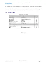
Page 12: ...ater back to the OMC Only master unit has modem slave unit remote monitor and control via RS485 2 4 KIT OF PARTS Table 1 Equipment KOP Product Identifier Description Quantity Mounting Rack RX 21232 58...

Page 13: ...ns flammable or explosive atmospheres the system must be suitably installed to prevent danger Protective Earthing Equipment provided for the purpose of protecting individuals from electrical risk must...

Page 14: ...having stable temperature and unrestricted air flow The installation location for the product should be well ventilated The equipment has been designed to operate at the temperature range and humidity...

Page 15: ...erference Reduce signal loss in feeder cable by minimizing the length and number of RF connections Ensure VSWR of antennas system 1 5 1 Ensure equipment will be operated within the stated environment...

Page 16: ...eady for installation If damage is discovered at the time of installation contact the shipping agent 3 3 2 TOOLS See Appendix A for a full list of the recommended tools required for installation and m...

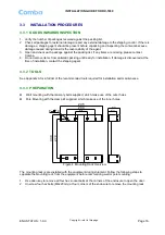
Page 17: ...e mounting rack to the wall using four masonry bolts M10x110mm Lift the enclosure onto the mounting rack and screw hex bolts M8x20mm to secure the enclosure to the mounting rack After local commission...

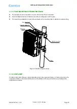
Page 18: ...k onto the pole The remaining installation to secure the enclosure to the mounting rack is identical to wall mounting Mounting Rack U Bolt M10X85X110 Enclosure M8X20 Hex Bolt Pole Figure 6 Pole Mounti...

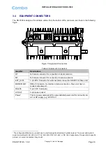
Page 19: ...ection to service antenna EXT_ALM 7 pin CPC Connector for external alarm connection RS485 for Slave unit MODEM ANT SMA F Connector for modem antenna connection Slave unit has no modem antenna port RS...

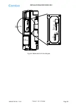
Page 20: ...STALLATION GUIDE FOR RX 1839 ENU STATUS 1 0 0 Copyright refer to title page Page 20 Commissioning Window Li ion Battery Box SIM MOD ALM RUN PWR LAN OFF ON ON BAT OFF Figure 8 Maintenance Window Diagra...

Page 21: ...green yellow Such a ground connection implements the Protective Ground Connection and must be connected to the equipment at the designated ground point In general do not connect the supply before esta...

Page 22: ...ation will be reported in case of power fault Figure 10 Maintenance Window Internal Layout 3 5 6 PHYSICAL CONNECTION TO OMT PC For local commissioning there is the method to connect the equipment with...

Page 23: ...Ds and a reset button are located on the MCU each indicates the status of a particular function Table 4 LED Indicators Identifier Colour Indication RUN Green MCU operation Flashes at a rate of 1 flash...

Page 24: ...commissioning procedure is as follows Connect and inquiry status Set channel No Input power detection and adjust the direction of Donor Antenna Output power confirmation Drive test and adjust the dir...

Page 25: ...Select Monitoring Parameters Select the equipment controlled and monitored parameters If the external devices are connected to the equipment for management please enable in the External Alarm Info Int...

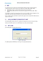
Page 26: ...ce how to apply local and remote connection to OMT for the first installation for the detailed OMT information please refer to OMT user manual and other references Notice The OMC software with remote...

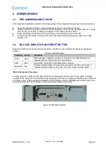
Page 27: ...ontrol Panel 5 4 LOCAL CONNETION TO OMT In order to access to equipment via Ethernet UDP the PC must be set with proper IP address and subnet mask in advance Figure 15 PC Protocol Setting The default...

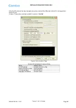
Page 28: ...se connect the Ethernet cable to PC and equipment Ethernet port Choose Connection via Ethernet UDP and click ONLINE Figure 16 Connection Type Table 6 IP Setting Quick Lookup Table Items Default Value...

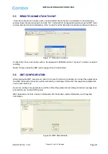
Page 29: ...phone number the password is 888888 and click connect it will be connected remotely Notice Please enable the SIM card to support Circuit Switch Data 5 6 OMT CONFIGURATION After entering the OMT main...

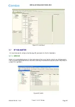
Page 30: ...ommended to configure the following RF parameters for the first installation 5 7 1 SWITCH Switch is to enable disable power for internal modules When user checks and sets non RF parameters such as che...

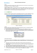
Page 31: ...el number within the setting range into the Setting column directly Right click the Setting column the Frequency Calculator dialogue window seen as below will pop up insert the desired channel number...

Page 32: ...ATT adjustment includes UL DL ATT adjustment The purpose of adjusting the ATT is to adjust system gain Figure 24 ATT Config Select the required value in setting columns of RF information window for AT...

Page 33: ...n setting columns of RF information window for Alarm threshold and press Enter or Config button to finish the configuration operation 5 7 5 POWER Power is referring to the reading of downlink input ou...

Page 34: ...k calculative gain Figure 27 Gain Read Press Read to read all the values of the parameters in the window Press Auto Read F4 to read values continuously 5 7 7 TEMPERATURE Figure 28 Temperature Read Pre...

Page 35: ...ds after that the switch will turn off automatically Figure 30 Miscellaneous 5 8 ALARM INFO Alarm information operation is to select alarm parameters for monitoring Alarm parameters include Master Ala...

Page 36: ...finish configuration operation Notice Enable box is to enable the alarm monitoring for system Only if users enable the alarm by ticking the Enable box the alarms can be monitored by the OMT OMC On th...

Page 37: ...nt identification It is a hexadecimal string of eight characters in the range of 00000000 FFFFFFFF e g 00000000 Site Sub ID Site Sub ID is used for Master Slave System It is the unique identification...

Page 38: ...Page 38 5 9 3 EQUIPMENT INFO Figure 36 Equipment Info 5 9 4 SITE LOCATION Figure 37 Site Location Site Location input the current longitude and latitude in the blank 5 9 5 SYSTEM CLOCK Figure 38 Syste...

Page 39: ...ion via Ethernet is not available at this stage Phone No This is designed for authentication purpose when remote connection via modem is required It is the phone number to dial the equipment Only the...

Page 40: ...INSTALLATION GUIDE FOR RX 1839 ENU STATUS 1 0 0 Copyright refer to title page Page 40 5 9 7 TRIGGER REPORT Figure 40 Trigger Report 5 9 8 UPDATE INFO Figure 41 Update Info End of Section...

Page 41: ...he equipment operation status can be observed remotely through OMC Periodic inspection of the repeater equipment s is recommended the recommended tasks includes Inspect and record operation status and...

Page 42: ...g are the recommended list of tools for new installation and routine maintenance Slotted Screwdriver Philips Screwdriver Ring Spanner Assorted size 12 20mm Electrically operated drill and masonry dril...

Page 43: ...INSTALLATION GUIDE FOR RX 1839 ENU STATUS 1 0 0 Copyright refer to title page Page 43 7 2 APPENDIX B RMA RETURN MATERIAL AUTHORIZATION FORM End of Section End of Document...

Page 44: ...INSTALLATION GUIDE FOR RX 1839 ENU STATUS 1 0 0 Copyright refer to title page Page 44...

Reviews: