INSTALLATION GUIDE FOR RX-1839
ENU STATUS : 1-0-0
Copyright - refer to title page
Page 23
4 COMMISSIONING
4.1
PRE-COMMISSIONING TASKS
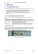
After equipment installation, perform the following steps before equipment powering and commissioning:
Check the expected voltage, current and power levels do not violate any ratings.
Visually inspect the power connection within the equipment. Ensure that the power cable is correctly
and securely connected, including grounding wire, RF cable and other cables.
Check grounding connection and verify that the ground resistance is less than 5
Ω.
Test the antenna system and ensure the echo loss within working frequency is less than -14dB
(VSWR<1.5).
4.2
MCU LED INDICATOR AND RESET BUTTON
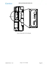
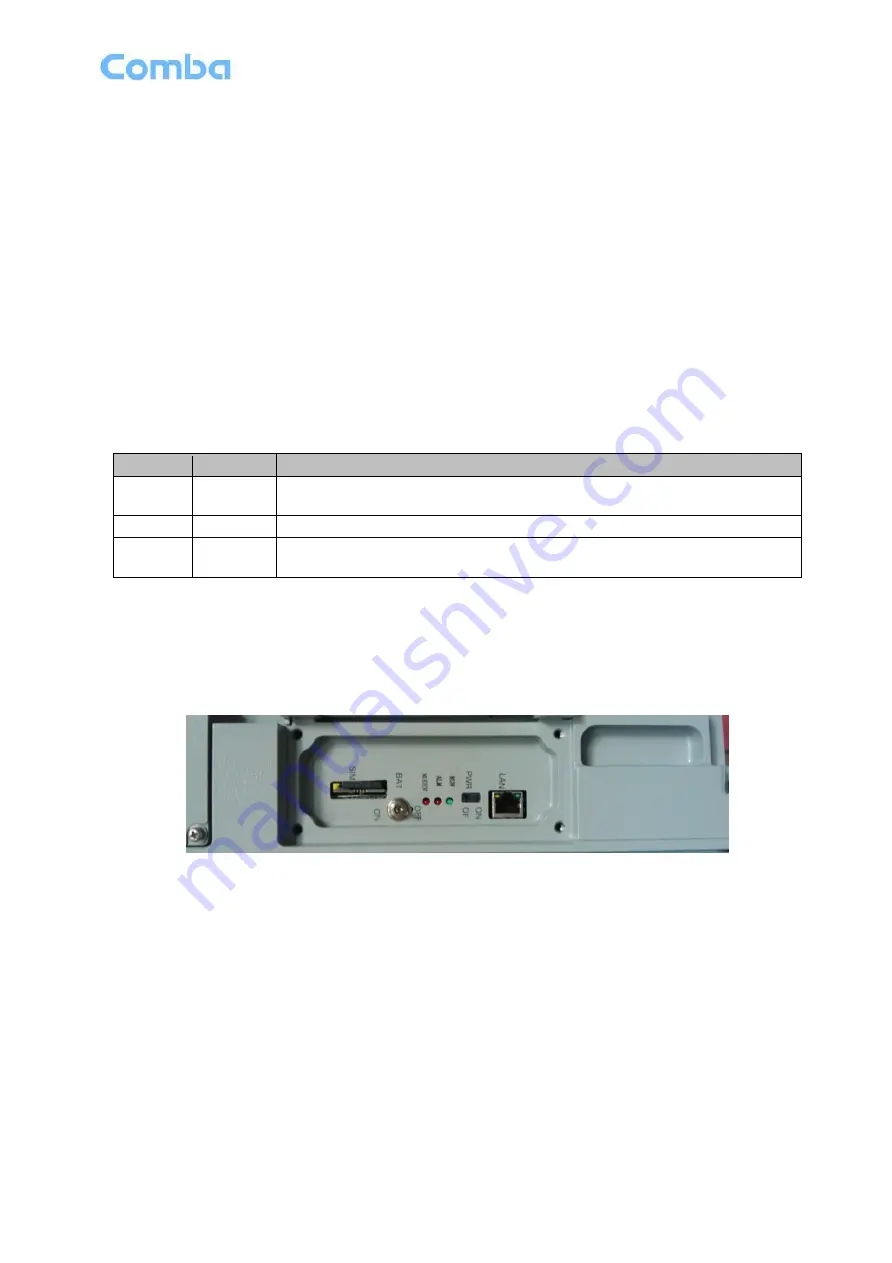
Diagnostic LEDs and a reset button are located on the MCU; each indicates the status of a particular
function:
Table 4: LED Indicators
Identifier Colour
Indication
RUN
Green
MCU operation. Flashes at a rate of 1 flash/sec. Any other flashing rate
indicates MCU is faulty, and has to be replaced.
ALM
Red
Alarm LED. When ON, it indicates alarm condition.
MODEM
Red
Wireless modem status. During normal operation, it is OFF. When ON, it
indicates faulty wireless modem and no communication will take place.
MCU Initialization Procedure
All three diagnostic LEDs of each MCU will flash simultaneously for three times when power is initially
supplied to the equipment. Then RUN will keep flashing at the rate of 1 flash/second.ALM will be ON when
any alarm occurs. After successful initialization of the wireless modem, MODEM will be ON for about two
minutes and then turn off; otherwise, it will remain ON to indicate a problem.
Figure 12: MCU Board LEDs


