background image

USER MANUAL FOR RX-2620 


ENU STATUS : 1-0-0 

Copyright - refer to title page 

Page 34


Summary of Contents for RX-2620

Page 1: ...L LT TE E W WI IR RE EL LE ES SS S R RE EP PE EA AT TE ER R USER MANUAL RX 2620 QE 1 0 0 Comba Telecom Ltd RX 2620...

Page 2: ...Comba International Comba All rights reserved The information contained herein is confidential and the property of Comba and is supplied without liability for errors or omissions No part may be repro...

Page 3: ...MOUNTING OF MOUNTING RACK 17 3 3 6 DRIP LOOP 17 3 4 EQUIPMENT CONNECTORS 18 3 4 1 CONNECTORS 18 3 4 2 GROUNDING CONNECTION 19 3 4 3 LI ION BATTERY CONNECTION 19 3 4 4 RF CONNECTION 19 3 4 5 EXTERNAL A...

Page 4: ...10 LEDs 21 Figure 11 PC Protocol Setting 24 Figure 12 Connection Type 1 25 Figure 13 Connection Type 2 25 Figure 14 Remote Connection 26 Figure 15 OMT Main Window 26 Figure 16 Switch 27 Figure 17 ATT...

Page 5: ...OR RX 2620 ENU STATUS 1 0 0 Copyright refer to title page Page 5 0 3 HISTORY Change No ENU Details Of Change 1 1 0 0 RX 2620 user manual first created in Aug 2012 and referred to its Chinese manual RX...

Page 6: ...al GSM Global Standard for Mobile Communication Hz Hertz ID Identification LNA Low Noise Amplifier MCU Main Control Unit MHz Megahertz MT Mobile Terminal MTBF Mean Time Between Failures NF Noise Figur...

Page 7: ...supplemented by safety notices in the appropriate equipment manual These notices contain additional information on the nature of the hazard and may also specify precautions Warning These draw the att...

Page 8: ...er detect functions easy for installation Automatic gain temperature compensation function which can maintain regular operation among working temperature It supports the remote download of monitoring...

Page 9: ...USER MANUAL FOR RX 2620 ENU STATUS 1 0 0 Copyright refer to title page Page 9 The following figure shows the enclosure of the RX 2620 420 330 182 Figure 1 Views of RX 2620 Enclosure End of Section...

Page 10: ...igure 2 RX 2620 System Diagram As shown in the above figure the downlink BS signals go through DT port to the system and then to downlink by duplexer separation The DL signals will go through LNA then...

Page 11: ...fier Functional Description Power Supply Unit PSU Converts the input voltage into a stable DC to provide power for the internal functional modules and to charge the internal Li ion battery Power Ampli...

Page 12: ...ier Description Quantity RX 2620 manual This equipment manual on CD Rom 1 CPC Connector X14J7P 1 Ethernet Cable 2m 1 Modem Antenna XD WCDMA 1 Masonry Bolt M8x80 4 U Bolt with 2 nuts flat washer spring...

Page 13: ...verse weather extreme temperatures wet corrosive or dirty conditions flammable or explosive atmospheres the system must be suitably installed to prevent danger Protective Earthing Equipment provided f...

Page 14: ...ation location for the product should be well ventilated The equipment has been designed to operate at the temperature range and humidity level as stated in the product specifications in the datasheet...

Page 15: ...nsit is the responsibility of the agent z Open and check each package against the packing list If any items are missing please contact Comba z Do not remove items from antistatic packing until ready f...

Page 16: ...Mounting rack as a guide z Insert the masonry bolts through the round holes and tighten them to take the weight of the entire enclosure z Hook the enclosure up onto the mounting rack and align the ho...

Page 17: ...ng rack onto the pole z The remaining installation to secure the enclosure to the mounting rack is identical to wall mounting U Bolt Pole Mounting Rack M8 Hex Socket Bolt Figure 6 Pole Mounting Overvi...

Page 18: ...ctor for external mobile antenna DT N female connector for external donor antenna EXT_ALM 7 pin CPC connector for external alarm interface POWER1 Power supply interface MODEM ANT SMA F connector conne...

Page 19: ...the system integrated module and MCU and connect the connectors as illustrated below after system commissioning to ensure the alarm message could be sent to OMC effectively in case of mains power fail...

Page 20: ...er off and Li ion battery output connector is disconnected 3 4 7 EXT ALARM CONNCETION The EXT ALARM port is a 7 pin CPC connector The following figure and table show the pin allocation and definition...

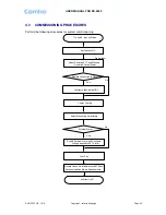
Page 21: ...ng connection and verify that the ground resistance is less than 5 Connect the equipment to the PC installed with OMT software Check antenna system return loss which working frequency band return loss...

Page 22: ...uiry Status External Alarm Yes Enable External Alarm and Configure Voltage applied to EXT Alarm Set Channel NO Adjust Downlink ATT and Measure Downlink Output Power Signal Input Exit from OMT Remote C...

Page 23: ...t controlled and monitored parameters z If the external devices are connected to the equipment for management please enable in the External Alarm Info Interface 7 Test coverage area field intensity an...

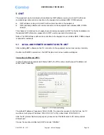
Page 24: ...ftware with remote connection to the equipment over wireless GSM CDMA network is optional for customers 5 1 LOCAL AND REMOTE CONNECTIONS TO OMT After installing OMT software on the PC connection to th...

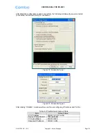
Page 25: ...nection via Ethernet UDP for connection Figure 12 Connection Type 1 Figure 13 Connection Type 2 After clicking ONLINE a window will pop up for user configuring IP Address and Port No Table 8 IP Settin...

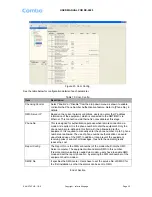
Page 26: ...nected remotely Notice Please enable the SIM card to support Circuit Switch Data 5 2 OMT CONFIGURATION After entering the OMT main screen click the Connect button on the toolbar to connect the equipme...

Page 27: ...finish the configuration operation 5 3 2 ATT ATT adjustment includes UL DL ATT adjustment The purpose of adjusting the ATT is to adjust system gain DL UL ATT 01setting range 0 30dB Figure 17 ATT Conf...

Page 28: ...nfig button to finish the configuration operation 5 3 4 ALARM INFORMATION Alarm information operation is to select alarm parameters for monitoring Alarm parameters include Master Alarm Channel Alarm a...

Page 29: ...iption Site ID Site ID is the unique equipment identification It is a hexadecimal string of eight characters in the range of 00000000 FFFFFFFF e g 00000000 Site Sub ID Site Sub ID is used for Master S...

Page 30: ...s the phone number to dial the equipment Only the phone number pre defined in this field will it be allowed to dial the equipment It is required to manually enter the phone number Up to 5 phone number...

Page 31: ...ment operation status can be observed remotely through OMC Periodic inspection of the repeater equipment s is recommended the recommended tasks includes z Inspect and record operation status and outpu...

Page 32: ...wing are the recommended list of tools new installation and routine maintenance Slotted screwdriver Philips screwdriver Ring spanner Assorted size 12 20mm Electrically operated drill and masonry drill...

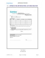
Page 33: ...USER MANUAL FOR RX 2620 ENU STATUS 1 0 0 Copyright refer to title page Page 33 7 2 APPENDIX B RMA RETURN MATERIAL AUTHORIZATION FORM End of Section End of Document...

Page 34: ...USER MANUAL FOR RX 2620 ENU STATUS 1 0 0 Copyright refer to title page Page 34...

Reviews: