background image

EQUIPMENT MANUAL FOR SP-2110 


SP-2110 QE 

Copyright - refer to title page 

Page 20

ENU Status : 1-3-1 


3.2  SITE PLANNING CONSIDERATIONS 

Site considerations 
 

The repeater is designed for indoor installation and operation.  
 

Installation location 
 

Mounting surface shall be capable of supporting weight of the equipment, allow 1.5Kg for the SP-
2110 equipment. Physical location should be able to achieve signal strength of better than -70dBm 
from the BTS antenna, and the MT antennas should provide the required coverage. 
 

Antenna separation 

 
For optimal operation, the physical separation of the MT and DT antennas should satisfy the condition 
for I > G

MAX

 +10dB, where I represents isolation between MT and DT ports. 


Environmental 
 

Humidity has an effect on the reliability of the equipment. It is recommended to install the equipment 
in location having stable temperature and un-restricted air-flow.  
 
SP-2110 equipment has been designed to operate at the temperature range from -20°c to +40°c with 
relative humidity at 

85%. 


Powering (AC mains supply) 
 

The external power supply unit provides power to all modules within the chassis. The equipment 
accepts 6VDC via an external PSU. 
 
In order to avoid electromagnetic interference, select the SP-2110 mounting location to minimize 
interference from electromagnetic sources such as: large electricity powered equipment. 
 

Grounding requirement 
 

Verify the equipment has been well grounded, this includes antennas and all cables connected. 
Ensure lightning protection for antennas is properly grounded.  


Cable routing 
 

The RF cables for SP-2110 have SMA (F) connectors; other cable connects the equipment with the 
external PSU. 


Manual handling 

 
During transportation and installation, take necessary handling precautions to avoid potential physical 
injury to the installation related personnel and/or damages to the equipment. 
 

Summary of Contents for SP-2110

Page 1: ...ational Documentation Centre Comba Telecom This is an unpublished work the copyright in which vests in Comba International Comba All rights reserved The information contained herein is confidential an...

Page 2: ...QUIPMENT LAYOUT 15 2 5 KIT OF PARTS 16 2 6 RF SPECIFICATIONS 17 2 7 POWER MECHNICAL AND ENVIRONMENTAL SPECIFICATIONS 18 3 INSTALLATION 19 3 1 WARNINGS AND ALERTS 19 3 2 SITE PLANNING CONSIDERATIONS 20...

Page 3: ...na 23 Fig 7 Mounting Arrangement 24 Fig 8 Wall mounting overview 24 Fig 9 Connecting to SP 2110 25 Fig 10 Dial Switches and MCU area 26 Fig 11 Location of LEDs 27 Fig 12 Function of dial switches 29 T...

Page 4: ...Details Of Change 1 1 0 0 Initial product identifier RS 3110 subsequently renamed Doc created on 14th September 2005 2 1 1 0 Revised for product update on 15th November 2005 3 1 2 0 KOP revised on 20t...

Page 5: ...EQUIPMENT MANUAL FOR SP 2110 SP 2110 QE Copyright refer to title page Page 5 ENU Status 1 3 1 0 5 ISSUE CONTROL Date 04 Oct 05 15 Nov 05 20 Feb 06 6 Apr 06 20 Mar 08 Section All all all KOP Spec all...

Page 6: ...title page Page 6 ENU Status 1 3 1 0 6 REFERENCES 0 6 1 RS 3110 V1 0 UMTS Pico Repeater Original manual released in August 2005 0 6 2 SP 2110 datasheet Issue C2 released on 21 Feb 2006 WCDMA Indoor Ba...

Page 7: ...Memory FS Frequency Selector FSA Frequency Selector Amplifier GSM Global System for Mobile Communication Hz Hertz ID Identification LNA Low Noise Amplifier MCU Main Control Unit MHz Megahertz MS Mobi...

Page 8: ...rmative text label may accompany the symbol label Hazard labeling is supplemented by safety notices in the appropriate equipment manual These notices contain additional information on the nature of th...

Page 9: ...TELECOM LTD Hong Kong Office Address 611 East Wing No 8 Science Park West Avenue Hong Kong Science Park Tai Po Hong Kong Tel 852 2636 6861 Fax 852 2637 0966 Email combahk comba telecom com Singapore O...

Page 10: ...any amendment remedial action can be carried out promptly we would appreciate your co operation in filling out and returning a photocopy of this customer reply sheet as soon as possible Customer Info...

Page 11: ...djustable and it s IF filtering provides superior out of band rejection Characteristics of the SP 2110 repeater are as follows System commission can be made manually without any additional equipment W...

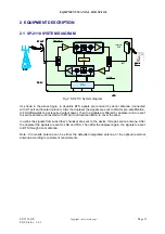
Page 12: ...2 SP 2110 System diagram As shown in the above figure in downlink BTS signals are received by donor antenna connected with DT port and located outdoor After the duplexer the signals are sent to LNA f...

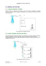
Page 13: ...tenna Refer to the figure below SP 2110 Integrated Antenna SP 2110 Integrated Antenna Fig 3 Application of Integrated Antenna 2 2 2 USING EXTERNAL ANTENNA OPTIONAL For extended coverage external anten...

Page 14: ...the working parameters of the repeater Integrated Antenna defaulted is used to transmit DL signals and receive UL signals Three Dial Switches for setup of Freq Control Freq Offset and Gain Located on...

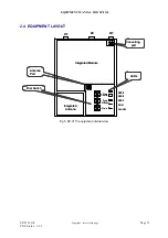
Page 15: ...eq Control Freq Offset Gain Dial Switch Antenna Converting ALARM RUN RSSI1 RSSI2 RSSI3 Integrated Module Integrated Antenna LEDs Port port DT DC MT Freq Control Freq Offset Gain Dial Switch Antenna Co...

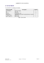
Page 16: ...PARTS For each SP 2110 the following are shipped Product Identifier Description Quantity PC 220602F0 DC Power Supply 1 6 Wall Plug 2 ST4X30 Self tapping screw 2 RS 31PICO SMA SMB jumper cable for ext...

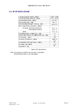
Page 17: ...Range 1 dB step dB 0 28 1 5 Max Output Power with ALC dBm Downlink With Internal Antenna With External Antenna Uplink 17 1 5 16 1 5 17 1 5 Pass Band Ripple 3 84MHz p p dB 2 System Noise Figure UL Max...

Page 18: ...AC 6VDC Power Consumption W 20 approx Dimensions L x W x H mm 235 x 150 x 54 Housing Material Plastic Aluminum Housing Color White Grey Anodized Weight kg 1 5 approx Connector Type SMA Operation Tempe...

Page 19: ...tems due to adverse weather extreme temperatures wet corrosive or dirty conditions flammable or explosive atmosphere then the system must be suitably installed to avoid such a danger Protective Earthi...

Page 20: ...n location having stable temperature and un restricted air flow SP 2110 equipment has been designed to operate at the temperature range from 20 c to 40 c with relative humidity at 85 Powering AC mains...

Page 21: ...erference Maintain reasonable distance from chassis to DT MT antennas Reduction of signal loss in feeder cable Suitable operating environment 20 C to 40 C Maximum 85 relative humidity Avoid direct sun...

Page 22: ...larity on the face of the carrier s receipt Without documentary evidence a claim cannot be processed Open and check each package against the packing list For any shortage contact Comba Telecom Systems...

Page 23: ...isconnect the integrated antenna from the Antenna Port Identify the jumper cable this is about 160mm in length and terminated by SMA and SMB connector Carefully install the jumper cable to bridge ante...

Page 24: ...apart by 45mm Depending on the mounting surface two 6 wall plugs may be needed insert and tighten two self tapping screws into the wall plugs leave the screw heads protruding by about 5mm Raise the ch...

Page 25: ...gned for all cable entries from the top of the chassis Fig 9 Connecting to SP 2110 Service voltage connection The repeater accepts 220VAC power The recommended DC connection is rated at 6VDC and has t...

Page 26: ...NG The equipment is easily commissioned once the cover is removed programming the equipment is by dial switches and visual feedback is by LED Reserved do not use Antenna port MCU reset Dial switches a...

Page 27: ...dicator which indicates the input field strength ON the DL input field strength is more than 60dBm OFF the DL input field strength is less than 60dBm RUN Green Operation ON normal operation flash duri...

Page 28: ...and selectivity can be proceeded with effectively within the 60MHz band of the WCDMA network It is adjusted based on the band width of the equipment Refer to table 9 for the comparison between the swi...

Page 29: ...CH5 CH4 CH7 CH8 CH9 CH10 CH11 CH12 CH6 Freq Control Software Set 0 8 4 C 1 2 3 5 6 7 9 A B D E F 0 100 200 400 300 600 700 700 600 500 500 400 300 200 100 kHz Freq Offset 0 8 4 C 1 2 3 5 6 7 9 A B D...

Page 30: ...onnect the power supply and recheck as above In this way if the ALARM is still ON and the signal coverage is unavailable contact Comba Telecom System Periodic inspection of the repeater equipment s is...

Page 31: ...tools required are for installing and fixing screws and tightening the SMA connectors Hereinafter is the recommended list for installation and routine maintenance Description Slotted screwdriver Phili...

Page 32: ...EQUIPMENT MANUAL FOR SP 2110 SP 2110 QE Copyright refer to title page Page 32 ENU Status 1 3 1 6 2 APPENDIX B RMA RETURN MATERIAL AUTHORIZATION FORM End of section End of Document...

Reviews: