EQUIPMENT MANUAL FOR SP-2110
SP-2110 QE
Copyright - refer to title page
Page 3
ENU Status : 1-3-1
0.3 INDEX TO FIGURES AND TABLES
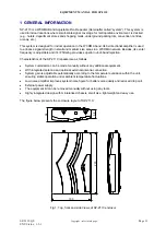
Fig 1: Top, front and side Views of SP-2110 enclosur .........................................................................11
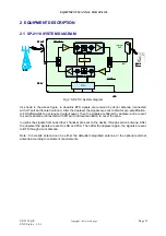
Fig 2: SP-2110 System diagram ...........................................................................................................12
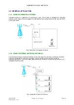
Fig 3: Application of Integrated Antenna...............................................................................................13
Fig 4: Application of External Antenna..................................................................................................13
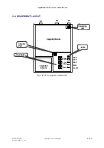
Fig 5: SP-2110 equipment internal view ...............................................................................................15
Fig 6: Conversion for External Antenna................................................................................................23
Fig 7: Mounting Arrangement ..............................................................................................................24
Fig 8: Wall mounting overview ..............................................................................................................24
Fig 9: Connecting to SP-2110...............................................................................................................25
Fig 10: Dial Switches and MCU area....................................................................................................26
Fig 11: Location of LEDs.......................................................................................................................27
Fig 12: Function of dial switches...........................................................................................................29
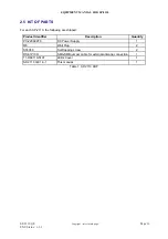
Table 1: SP-2110 KOP .........................................................................................................................16
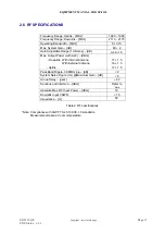
Table 2: RF specifications.....................................................................................................................17
Table 3: Power, Mechanical and environmental specifications ............................................................18
Table 4: Repeater Installation checklist ................................................................................................21
Table 5: Antenna installation checklist..................................................................................................21
Table 6: LEDs colour and indication .....................................................................................................27
Table 7: SP-2110 system commissioning procedures .........................................................................28
Table 8: Comparison between swich-setted working channel and actual working channel ................29

