Omega II
®
Installation, Operation & Maintenance
Combustion Research Corporation
Page 19
COMBUSTION AIR SUPPLY
NOTICE
Air that is not contaminated must be ducted to the
heater if chlorinated or fluorinated contaminants, high
humidity, other contaminants, or if negative pressure is
present in the area where the heater is installed.
1. Combustion air is a factory preset opening.
2. It is recommended that outside combustion air be used.
However, combustion air may be drawn from any space,
including the space that is being heated, PROVIDED
the building does not have a negative pressure and the
atmosphere is not contaminated with acid fumes,
fluorocarbons, corrosive substances, dirt, oil, etc., which
would have an adverse effect on the blower and radiant
tubing. DO NOT draw combustion air be drawn from an
attic space.
3. If outside air combustion air is not used and the room in
which the heater is used is of a tight construction,
provisions must be made for supplying combustion air.
One square inch of free area opening for each 5,000
Btu/hr input is required to replenish the air used by the
heating system.
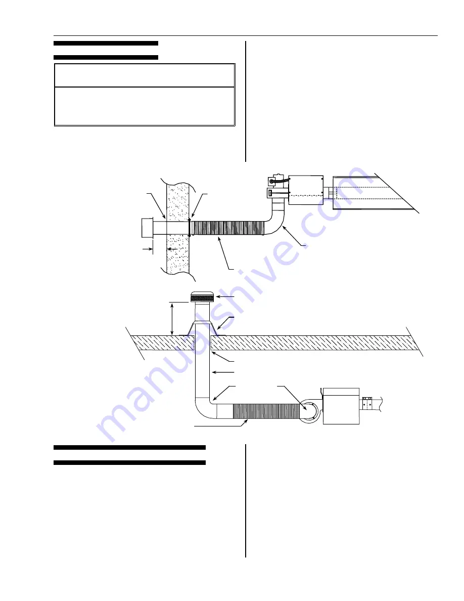
OUTSIDE AIR SUPPLY (RECOMMENDED)
1.
The outside air intake assembly (PN 0314.00) consists
of: 1 - 4" OD inlet hood, I - 4" OD 24" long inlet flex and
2 clamps.
2.
The assembly may be extended by adding up to 20' of
the appropriately sized ducting. A maximum of two
elbows may be used. Insulating the ducting will stop
condensation from forming on its exterior.
3.
Air intake may be made through the roof using
"mushroom" type vent cap.
4.
Maintain a minimum of six (6') between the exhaust port
and the fresh air inlet port.
5.
Maintain a minimum of six inches (6") the inlet hood and
the exterior wall.
6.
DO NOT DRAW COMBUSTION AIR FROM ATTIC OR
SIMILAR SPACE. DO NOT USE PLASTIC TYPE
"DRYER" FLEX FOR THE COMBUSTION AIR INLET
FLEX.
7.
The air intake terminal must be located not less than
one foot (1') above grade.
NOTE
– Avoid installing inlet flex as an elbow into the
blower and DO NOT install inlet flex as an elbow into the
blower on burners with inputs of 155,000 Btu/hr and higher
- system pulsation can occur.
ROOF
PENITRATION
(SIDE VIEW)
No clearance required
4” Combustion air duct by installer
4” Elbow by
installer
Roof flashing
Min. 4” Inlet cap
Min. 2’
4” Flex
SIDE WALL
PENITRATION
(TOP VIEW)
Concrete nails
or screws
4 places
Install 4” dia. Inlet flex
nearest wall
Use 4” sheet metal of PVC
extension and elbow on inlet
to blower
Min. 6”
Caulk
Summary of Contents for Omega II
Page 40: ...Omega II Installation Operation Maintenance Page 36 Combustion Research Corporation...
Page 48: ......
Page 49: ......


