Omega II
®
Installation, Operation & Maintenance
Combustion Research Corporation
Page 33
5. The sensing probe detects the presence of the low fire
flame and the control de-energizes the spark and the
valve will remain open. Check valve outlet and other
downstream pipe connections with a soap solution.
6. Turn the thermostat to a low dial setting to open
contacts. The main gas flame should be extinguished.
7. For 100% shutoff check, set thermostat to low dial
setting (system off). Disconnect sensing probe lead at
control terminal.
8. Turn thermostat to a high dial setting to energize spark
ignition and valve. The gas should ignite. After 30
seconds, the system should "lockout" and burner
functions are off (no gas flow, no spark). If the system
does not go into "lockout," follow the installation
instructions to replace the control. Repeat the 100%
shutoff check. Note blower will not shut down when
ignition "lockout" occurs.
9. Set thermostat again to a low dial setting (system off),
connect probe lead to control terminal. Set thermostat
to normal setting to put system back in service.
CHECK SAFETY SHUTDOWN PERFORMANCE
WARNING
FIRE OR EXPLOSION HAZARD
IMPROPER INSTALLATION, ADJUSTMENT,
ALTERATION, SERVICE OR MAINTENANCE
CAN CAUSE DEATH, SEVERE INJURY
AND/OR PROPERTY DAMAGE.
Perform the safety shutdown test anytime work is done
on a gas system
.
NOTE: Read steps 1-7 below before starting safety
shutdown or safety lockout tests for the ignition module.
1. Turn gas supply off.
2. Set the thermostat or controller above room temperature
to call for heat.
3. Watch for ignition spark immediately or following pre-
purge. See ignition module specifications.
4. Time length of ignition operation. See ignition module
specifications.
5. After the module locks out, open gas control and ensure
there is no gas flow to main burner.
6. Set the thermostat below room temperature and wait
one minute.
7. Operate system through one complete cycle to ensure
all controls operate properly.
IGNITION CHECKOUT PROCEDURES
A combination voltmeter and micro-ammeter with a DC
micro-ammeter range setting of 0 to 10 micro-ampere is
required. Follow meter instructions for proper use. TO
CHECK AC VOLTAGES:
1. Set range selection switch to 150V AC before
connecting leads.
2. Connect wire leads in parallel with voltage to be
measured.
3. Read voltage on AC scale.
TO CHECK CURRENT FROM FLAME SENSING
PROBE:
1. Set range selector switch to 10 micro-amperes before
connecting leads.
2. Turn off power supply to ignition control.
3. Disconnect sensing probe cable from sensor terminal or
ignition control.
4. Connect red (positive) meter lead to sensor terminal.
5. Connect black (negative) meter lead to probe cable.
6. Turn on electrical supply to system and cycle system
through the thermostat.
7. After system has ignited, the meter should read 0.7
micro-amperes or higher. If less than 0.7 micro-
amperes, the control may need to be replaced. Check
all wiring connections before replacing control.
8. Turn off supply voltage.
9. Disconnect meter from sensor terminal and probe cable.
10. Reconnect probe cable to sensor terminal.
11. Turn on supply voltage.
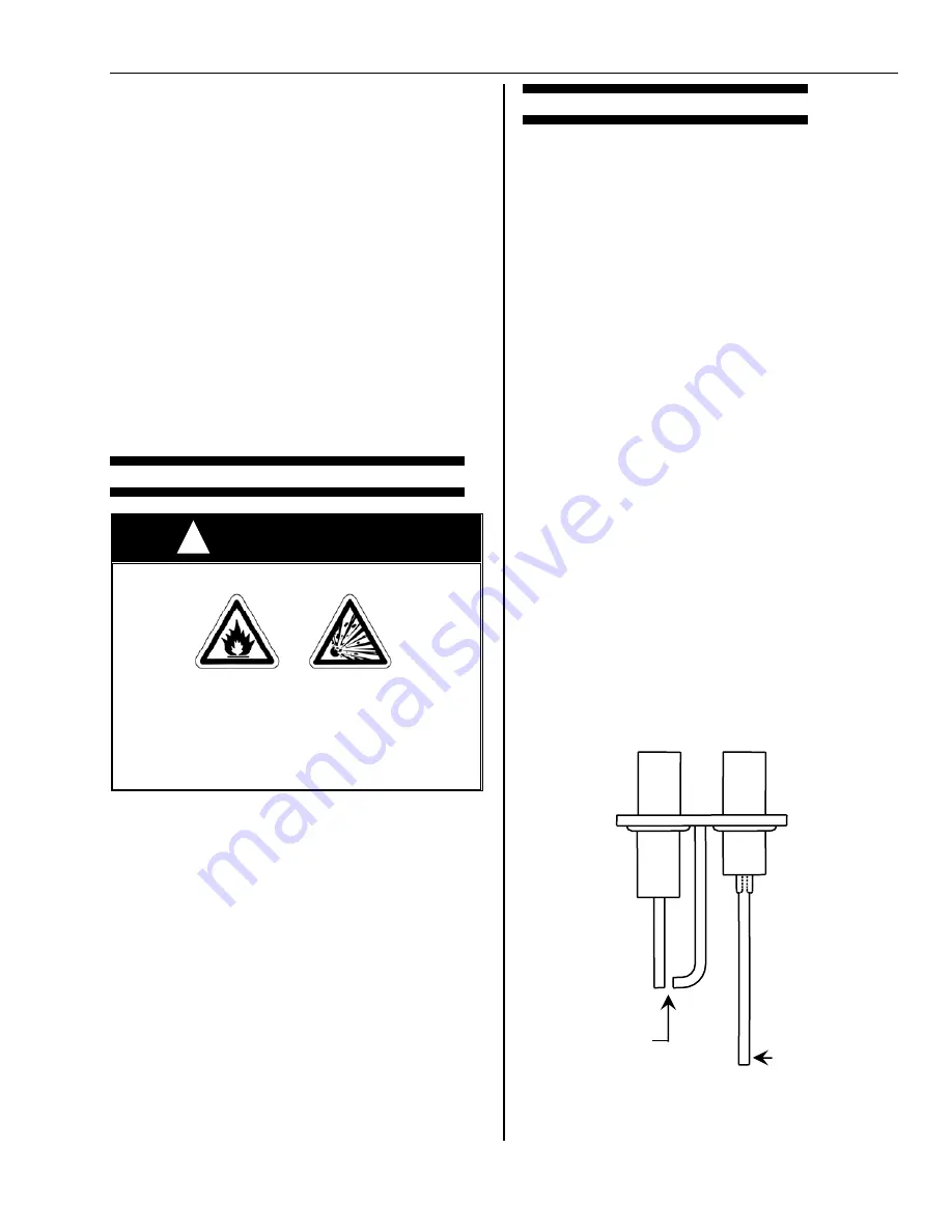
IGNITOR / FLAME SENSOR
0.10” Spark gap
Flame sensor
!
Summary of Contents for Omega II
Page 40: ...Omega II Installation Operation Maintenance Page 36 Combustion Research Corporation...
Page 48: ......
Page 49: ......


