Reflect-O-Ray
®
Oil Fired EDS 3.5
Installation, Operation & Service
Page 26
Combustion Research Corporation
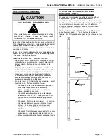
VENTING ARRANGEMENTS
WARNING
IMPROPER INSTALLATION CAN CAUSE
DEATH, SEVERE INJURY AND/OR
PROPERTY DAMAGE.
Improper venting and insufficient ventilation may result
in health problems, carbon monoxide poisoning and
death. Vent enclosed spaces and buildings according
to national, state, provincial and local codes.
♦
This radiant heater must be vented in accordance with
national, state, provincial and local codes and the
guidelines in this manual. In the United States refer to
the latest edition of the ANSI Z223.1 (NFPA 54)
Standard and in Canada refer to the latest edition of the
CAN/CGA B149.2 Standard.
♦
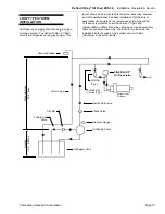
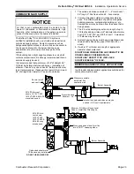
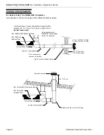
The layout drawing shows the general location of the
vacuum exhauster. Specific exhauster location and
discharge details must meet the following criteria:
♦
Make sure that the venting method selected is in
compliance with local codes.
♦
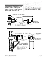
Heater may be vented to the outdoors vertically or
horizontally. The vent piping shall be adequately
supported to prevent sagging.
♦
Horizontal discharge is preferred through side walls.
The footage of horizontal vent pipe should be calculated
into the maximum system footage as outlined in the
charts on page 3. Vertical discharge must be arranged
as shown on page 28.
♦
Where the vent pipe passes through areas where the
ambient temperature is likely to induce condensation of
the flue gases the vent pipe shall be insulated.
♦
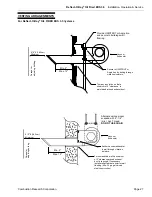
If the heater is to be vented horizontally:
a. Vent must terminate at least 3 feet (0.9m) above any
forced air inlet located within 10 feet (3.1m).
b. Vent shall terminate at least 4 feet (
1.2m
) below, 4
feet (
1.2m
) horizontally from, 1 foot (
30cm
) above any
door, window, or gravity air inlet into any building.
c. The bottom of the vent terminal shall be located at
least 12 inches (
30cm
) above grade and at least 6
inches (
15cm
) above anticipated snow depth.
d. Distances from adjacent public walkways, adjacent
buildings openable windows and building openings, are
to be consistent with ANSI Z223.1 (NFPA 54) Standard
and the CAN/CGA B149.2 Standard.
e. Vent must not terminate less than 6-ft
(1.8m
) from a
combustion air inlet of another appliance.
f. Vent must not terminate above a gas utility meter or
service regulator.
g. Vent terminal shall not be less than 7-ft
(2.1m)
above
grade.
♦
Vent opening must be beyond any combustible
overhang.
♦
Any portion of the flue pipe that passes through
combustible material of the building must have a
minimum 1" clearance.
♦
If condensation within the flue becomes a problem, the
flue should be shortened or insulated.
♦
Building materials should be protected from degradation
by flue gas products.
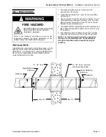
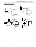
Recommended practice is to mount the vacuum exhauster
on the building inside wall. Alternatively the vacuum
exhauster may be suspended from the ceiling.
The vacuum exhauster can be mounted outside either on
roof or out side wall. The vacuum exhauster must be
protected from weather by mounting a hood over the
entire assembly. Vacuum exhausters are shipped
completely assembled. Scroll can only be rotated in 90°
increments.
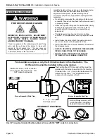
The vacuum exhauster shall be installed so that the
discharge is bottom horizontal. Any other arrangement
will permit condensation to collect in scroll and cause
premature failure of scroll. For minimum corrosion of
scroll when mounted outside and the metal temperature of
the scroll is less than 150°F, it is recommended that the
casing be suitably insulated for protection against the
weather.
Motor and exhauster impellers are precision balanced and
bench tested as a complete assembly for vibration and
noise. It is important that care be used when handling the
vacuum exhauster to insure that it is not put out of balance
by dropping or careless handling.
Install the vibration isolating stainless steel flex (PN
0334.SS) as may be shown in the layout drawing. The
stainless steel exhaust flex is to be installed in a straight
line, rather than formed into an elbow.
The PN 0219.00 & 0419.00 exhaust vents are provided
with stainless steel bird screen as standard when
furnished by Combustion Research Corporation.
OPERATION
1. Before connecting the motor to the electric supply,
check the electrical characteristics as indicated on
the motor nameplate to insure proper voltage, phase,
and rotation.
2. After electrical connections are completed,
momentarily apply power, just enough to start the
vacuum exhauster unit. Be sure that the rotation of
the wheel is correct as indicated by directional arrows
on the unit. If proper rotation, apply full electrical
power.
3. With the complete system in full operation and all
ducts attached, measure current input to the motor
and compare with the nameplate rating to determine
if the motor is operating under safe load conditions.
!


