Reflect-O-Ray
®
Oil Fired EDS 3.5
Installation, Operation & Service
Combustion Research Corporation
Page 35
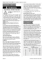
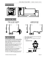
SEQUENCE OF OPERATION
1. Thermostat calls for heat.
2. Vacuum exhauster is energized.
3. Differential airflow switch proves that operation of the
exhauster and the ignition control is energized.
4. After pre-purge timing, the spark igniter and oil valve
are energized.
5. The ignition control senses the flame (Cad Cell) and
turns off the spark ignition.
6. After the thermostat is satisfied the power is removed
from the burner assembly causing the ignition control,
oil solinoid valve and vacuum exhauster to be de-
energized.
6. System waits for the next call for heat.
OPERATION
Before connecting the system to the electric supply, check
the electrical characteristics as indicated on the Rating /
Nameplate to insure proper voltage and oil supply.
With the system completely assembled, all ducts attached
and in full operation, measure current input to the motor
and compare with the nameplate rating to determine if the
motor is operating at safe load conditions and not
overloaded.
GENERAL SAFETY INFORMATION
1. Follow all local electrical and safety codes, as well as
the National Electrical Code (NEC) and the
Occupational Safety and Health Act (OSHA).
2. Burner(s) and vacuum exhauster must be securely and
adequately grounded. This can be accomplished by
wiring with a grounded, metal-clad raceway system, by
using a separate ground wire connected to the bare
metal of vacuum exhauster frame, or other suitable
means;
3. Always disconnect power source before working on or
near a motor or its connected load. If the power
disconnect point is out-of-sight, lock it in the open
position and tag to prevent unexpected application of
power.
4. Be careful when touching the exterior of an operating
motor. It may be hot enough to be painful or cause
burn injury. With modern motors, this condition is
normal when operating at rated load and voltages.
Modern motors are designed to operate at higher
temperatures.
5. Protect the power cable from coming in contact with
sharp objects.
6. Do not kink power cable and never allow the cable to
come in contact with oil, grease, hot surfaces, or
chemicals.
7. Make certain that the power source conforms to the
requirements of your equipment.
8. When cleaning electrical or electronic equipment,
always use an approved cleaning agent such as dry
cleaning solvent.
9. Not recommended or certified as an explosion proof
blower.
MAINTENANCE
WARNING: ALWAYS DISCONNECT POWER SUPPLY
BEFORE SERVICING THE BLOWER OR WORKING
WITH THE UNIT FOR ANY REASON. THIS IS
ESPECIALLY IMPORTANT WITH UNITS EQUIPPED
WITH AUTOMATIC RESET THERMAL PROTECTION.
UNIT MAY ACTIVATE WITHOUT WARNING!
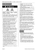
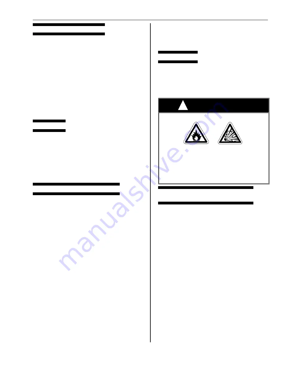
WARNING
FIRE OR EXPLOSION HAZARD
IMPROPER INSTALLATION, ADJUSTMENT,
ALTERATION, SERVICE OR MAINTENANCE
CAN CAUSE DEATH, SEVERE INJURY
AND/OR PROPERTY DAMAGE.
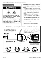
Use only clean filtered #2 Fuel Oil. Do not attempt to
burn waste oil of any sort, garbage or paper in the
burner assembly.
PRE-CONDITlONS TO BE CHECKED
BEFORE BURNER SYSTEM STARTUP
1. System has been installed to Combustion Research
Corporation recommendations in Installation Manual
and nameplate data.
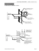
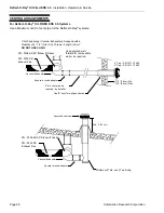
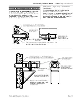
2. The system as installed must be installed with
adequate clearance to combustibles as outlined in this
manual. In storage areas where stacking of materials
may occur, the installer must provide signs that specify
the maximum stacking height so as to maintain the
required clearance to combustibles.
3. Electrical input to each heating zone is typically a 20 to
30-amp service, 115V AC/60 HZ (1-Ph).
a. All main disconnects closed and fuses OK.
b. All service disconnect switches at each burner and
exhauster turned on.
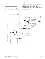
4. Fuel oil supply system is free of leaks and fitted with
fusible oil valves and oil filters.
5. Fuel oil supply system is free of leaks and fitted with
fusible valves and oil filters.
6. All valves and fusible link valves are open. All feed
lines must be purged clean and full of oil.
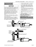
7. Exhauster has been checked for fan rotation, clockwise
viewed from motor end.
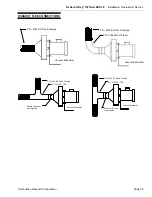
8. Flex connection to fan inlet secure and free of leaks.
9. Blast damper pinned, secured and set so that the
vacuum cannot be altered.
!

