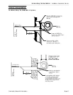
Reflect-O-Ray
®
Oil Fired EDS 3.5
Installation, Operation & Service
Combustion Research Corporation
Page 41
SETTING THE AIR ADJUSTMENT
PLATE
Riello 40, F3 (After December, 2002)
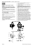
The electric air shutter assembly (1) is operated
on 120v, 60Hz gear driven motor, and the burner
motor will not operate until the air shutter is in its
full open position.
To adjust the air plate (4), loosen the center air
shutter screw (5) and the side plate screw, move
air plate (4) by using the adjustment arm on the
air plate.
The proper number on the air plate should line up
with the arrow (2) on the fan housing cover.
Refer to page 34 for proper settings. Retighten
screws (3) & (5).
1
2
3
4
5
Riello 40, F3 (Pre December, 2002)
The hydraulic AIR Shutter (1) is operated by the HYDRALIC JACK
(6), assuring complete opening of the air intake. To adjustment the
manual AIR ADJUSTMENT PLATE (4) loosen the FIXING
SCREWS (3 & 5). The setting of the air adjustment plate is listed
on page 34.
The proper number on the manual AIR ADJUSTMENT PLATE (4)
should line up with the SETTING INDICATOR (2) on the fan
housing cover. Once set, this plate must be secured in place by
tightening SCREWS 3 & 5. Manually open and release the
hydraulic air shutter to ensure it has free movement.
1
2
3
4
5
4
TURBULATOR SETTING
Loosen NUT (1) and then turn Screw (2) until the
INDEX MARKER (3) is aligned with the correct
index number as shown on page 34.
Re-tighten the RETAINING NUT (1).
NOTE: Zero (0) and three (3) are the scale indicators only.
From left to right, the first line is 3 and the last line is 0.
3
0
3
3
2
1
0
ELECTRODE SETTING
Remove the drawer assembly as described on page 40 to gain access to the spark assembly. Do not force or over tighten
screws, as damage to porcelain will occur.
5/32”
5mm
13/64”
5mm
5/64” – 7/64”
2 – 2.5mm

