Reflect-O-Ray
®
EDS 6
Installation, Operation & Service
Combustion Research Corporation
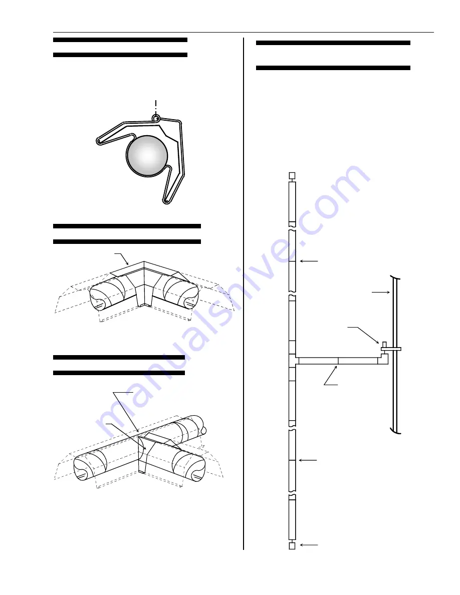
REFLECTOR ANGLE MOUNTING
The combination hangers are designed so that the
suspension hardware can be attached either in the center
or to one side that will position the tube and reflector
assembly up to a maximum 30° angle. This angle can be
reduced if required by use of a tie strap.
REFLECTOR ELBOW CONNECTION
REFLECTOR TEE CONNECTION
TYPICAL REFLECTOR LAYOUT WITH
EXPANSION JOINTS
An overlapping expansion joint consists of a reflector
overlap without being secured together. This allows for
freedom of movement or expansion during normal heat up
and cool down. Expansion joints are to be placed at
approximately the center of each straight run of reflectors
with a maximum of three (3) reflectors connected together.
Additional expansion joints in each straight run may be
necessary.
All other reflector joints, reflector elbows and reflector tee's
should be overlapped 1 - 2" and sheet metal screwed
together, DO NOT position an expansion joint at an elbow
or tee.
Burner
Expansion
Joint
Expansion
Joint
Expansion
Joint
Building
Wall
Vacuum
Exhauster
Use Sheet Metal Screws To
Secure "Tee" In Place
Field Cut Reflector To Provide
Clearance For Radiant Tube
Reflector
Reflector Elbow
Secure To Connecting Reflector
With Sheet Metal Screws
Maximum Mounting
Angle - 45°
Page 13


