System Programming
66-083
PROCEDURE
1.
2 .
3 .
4 .
5 .
Determine the system programming parameters,
and record them for future reference.
Turn on the AC power to the system and the
VDT.
Press the RETURN (ENTER) key. The system
enters an approximate 20 second timeout cycle.
Step 4 must be performed within this timeout period
or the programming sequence will be aborted.
Type the password: I
7 4 6
and press
RETURN
(ENTER). The VDT will display the main
programming menu. The system enters an
approximate 3 minute timeout cycle. A selection or
response must be entered within this timeout
period, otherwise; the programming sequence is
aborted.
Execute the programming procedures by
responding to the prompts listed in first the main
menu and then in subsequent menus.
REMOTE PROGRAMMING
The telephone system can be programmed remotely
using the following equipment:
A VDT or a PC and appropriate software program,
A pair of data modems.
The data modems can be any commercially available
300 or
200 baud type with auto-answer
capability. Be sure to verify the auto-answer capability
before purchasing the units.
is recommended that
the same make and model of modem be used at both
the installation site and the remote programming site.
INSTALLATION
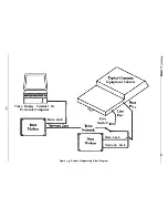
The equipment connections at the customer location
are as illustrated in
Figure 4-3
on page 4-80, Connect
the equipment for remote programming as illustrated
therein and discussed below.
Determine the signal needs of the modem from the
user’s manual for it.
Wire the proper connector (to match the data jack)
on one end of a length of multiline cable.
Punch down the appropriate leads on the connector
block.
Refer to Chapter 3 for connection details as
needed.
Connect the network jack of the data modem to an
outside telephone line. (If a line is not reserved for
remote programming, a line
can be installed
so that an outside telephone line can be switched
by on-site personnal between the data modem and
the common equipment cabinet when remote
programming is to be done.)
Refer to the user’s manual for the modem, and
program the modem to automatically answer after
the first ring.
Interface the VDT or PC with the modem at the
programming site per the user’s manuals for the
equipment be used.
OPERATION
To establish a communications link for programming
the system from a remote site, proceed as follows:
If a line switch is being employed, call someone at
the customer site, and ask that the switch be set for
modem operation.
After the outside line is connected to the modem,
the data link can be made between the originating
and the remote modems.
Programming can then be performed from the remote
site just as if the VDT or PC was connected directly to
the system.
TYPICAL PC OPERATION
The following procedure is given as a typical example
for using a PC and an XMODEM-type communications
software program to program the telephone system. It
is only provided for illustration and reference purposes
and describes a set-up using a typical
communications software program known as
PROCOMM
(produced by Datastorm Technologies,
Inc.). Many other communications software programs
are also available which can be used for this purpose.
Individual operating procedures may vary with
different communications software programs but the
general process is similar to this.
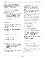
1. Perform turn-on and program-load procedures.
operating through modems, take action, as
described in the previous discussion, to establish a
communications link between the PC and the
common equipment.
4-84
Summary of Contents for DIGITECH
Page 13: ...System Overview l 6 ...
Page 14: ..._ d33 System Overview J 0 I r0 0 0 t 0 0 0 0 0 0 0 0 0 l 7 ...
Page 41: ...IMI 66 083 Table 3 2 J l Statlon Connections 4 Line Station Base Unit SPARE PORTS ...
Page 47: ...IMI 66 083 Installat ...
Page 55: ...IMI66 083 Installat llllllilliiiiiliiiil5 TTTTTTITTTTTTTTTTTTT 1111111111111111111 E 3 21 ...
Page 62: ...installation IMI 66 083 Figure 3 16 Software Cartridge lnstallatlon and Removal 3 28 ...
Page 106: ...System hogramming IMI 66 083 STATION LINECONFIGURATIONRECORD ...
Page 110: ......
Page 111: ......
Page 112: ......
Page 113: ......
Page 137: ...LAST RESORT TABLE I U L COST T U 1 31TME 1 RATE q 2 RATF ICHARGE R2RATF 1 1 SURCHARGE 1 I ...
Page 138: ...COST TABLE 20 I SURCHARGE I 2 RATF SURCHARGE ...
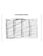
Page 146: ...SYSTEM SPEED DIAL RECORD ...
Page 181: ...Sjlstem Gperation IMI 66 083 ...


