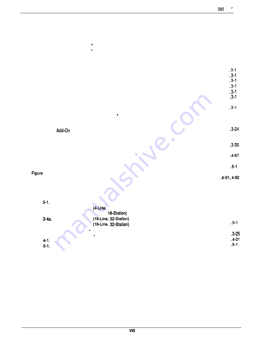
Table Of Contents
66
Figure l-1.
O u t l i n e D i m e n s i o n s Common Equipment
. . . . . . . . . . . . . . . . . . . . . . . . . . . . . . .
l-5
Figure l-2.
O u t l i n e D i m e n s i o n s Station Equipment
. . . . . . . . . . . . . . . . . . . . . . . . . . . . . . . .
l-6
Figure 1-3.
Station Images
. . . . . . . . . . . . . . . . . . . . . . . . . . . . . . . . . . . . . . . . . . . . . .
l - 7
Figure 3-l.
Mounting Dimensions
. . . . . . . . . . . . . . . . . . . . . . . . . . . . . . . . . . . . . . . . . .
3-2
Figure 3-2.
AC Power Connection And System Grounding
. . . . . . . . . . . . . . . . . . . . . . . . . . . . .
3-4
Figure 3-3.
Common Equipment, Station And Line Connections
. . . . . . . . . . . . . . . . . . . . . . . . .
1
Figure 3-4.
Typical Line Connections
. . . . . . . . . . . . . . . . . . . . . . . . . . . . . . . . . . . . . . . .
2
Figure 3-5.
Typical Station Connections
. . . . . . . . . . . . . . . . . . . . . . . . . . . . . . . . . . . . . .
3
Figure 3-6.
K e y / H y b r i d C o n f i g u r a t i o n
. . . . . . . . . . . . . . . . . . . . . . . . . . . . . . . . . . . . . . .
4
Figure 3-7.
Power Failure Connection
. . . . . . . . . . . . . . . . . . . . . . . . . . . . . . . . . . . . . . .
5
Figure 3-8.
Auxiliary Interface Connections
. . . . . . . . . . . . . . . . . . . . . . . . . . . . . . . . . . . .
6
Figure 3-9.
T y p i c a l C o m m o n A u d i b l e I n t e r f a c e W i r i n g
. . . . . . . . . . . . . . . . . . . . . . . . . . . . . . .
3-l 7
Figure 3-l 0.
Typical External Paging Connection
. . . . . . . . . . . . . . . . . . . . . . . . . . . . . . . . . .
8
Figure 3-l 1.
Typical External Paging Connection
Line Port
. . . . . . . . . . . . . . . . . . . . . . . . . . . .
3-l 9
Figure 3-12.
T y p i c a l D a t a D e v i c e C o n n e c t i o n s
. . . . . . . . . . . . . . . . . . . . . . . . . . . . . . . . . . .
.3-21
Figure 3-13.
Music Interface
. . . . . . . . . . . . . . . . . . . . . . . . . . . . . . . . . . . . . . . . . . . . .
.3-22
Figure 3-l 4.
Expansion Module Configuration
. . . . . . . . . . . . . . . . . . . . . . . . . . . . . . .
Figure 3-l 5.
Expansion Module Installation
. . . . . . . . . . . . . . . . . . . . . . . . . . . . . . . . . . . . .
.3-26
Figure 3-l 6.
Software Cartridge Installation and Removal
. . . . . . . . . . . . . . . . . . . . . . . . . . . . .
3-28
Figure 3-l 7.
D a t a C o m m u n i c a t i o n s I n t e r c o n n e c t i o n D i a g r a m
. . . . . . . . . . . . . . . . . . . . . . . . . . . .
Figure 4-l.
L o c a t i o n O f K e y s O n T e l e p h o n e F a c e p l a t e
. . . . . . . . . . . . . . . . . . . . . . . . . . . . . .
4-49
Figure 4-2.
C a l l C o s t i n g D i a g r a m . . . . . . . . . . . . . . . . . . . . . . . . . . . . . . . . . . . . . . . . . .
Figure 4-3.
R e m o t e P r o g r a m m i n g B l o c k D i a g r a m
. . . . . . . . . . . . . . . . . . . . . . . . . . . . . . . . .
.4-86
Figure 5-l.
C o n t r o l s a n d I n d i c a t o r s . . . . . . . . . . . . . . . . . . . . . . . . . . . . . . . . . . . . . . . . .
8
6-1.
Station Wall Mounting Details
. . . . . . . . . . . . . . . . . . . . . . . . . . . . . . . . . . . . . .
6-2
Programming Overlays
. . . . . . . . . . . . . . . . . . . . . . . . . . . . . . . . . . . . . . . . . . . . .
LIST OF TABLES
LIST OF ILLUSTRATIONS
Table
Line Connections . . . . . . . . . . . . . . . . . . . . . . . . . . . . . . . . . . . . . . . . . . . . .
3-6
Table 3-2.
S t a t i o n C o n n e c t i o n s
E-Station)
. . . . . . . . . . . . . . . . . . . . . . . . . . . . . . . . .
3 - 7
Table 3-3.
Station Connections (E-Line,
. . . . . . . . . . . . . . . . . . . . . . . . . . . . . . . .
3-8
Table
S t a t i o n C o n n e c t i o n s
. . . . . . . . . . . . . . . . . . . . . . . . . . . . . . . .
3-9
Table 3.4b.
S t a t i o n C o n n e c t i o n s
. . . . . . . . . . . . . . . . . . . . . . . . . . . . . . .
0
Table 3-5.
Line Connections 408 Expansion Module
. . . . . . . . . . . . . . . . . . . . . . . . . . . . . .
3-23
Table 3-6.
S t a t i o n C o n n e c t i o n s 408 Expansion Module
. . . . . . . . . . . . . . . . . . . . . . . . . . . . .
Table
C h a r a c t e r D i a l i n g C o d e s C h a r t
. . . . . . . . . . . . . . . . . . . . . . . . . . . . . . . . . . . .
Table
Character Codes
. . . . . . . . . . . . . . . . . . . . . . . . . . . . . . . . . . . . . . . . . . . .
6
Summary of Contents for DIGITECH
Page 13: ...System Overview l 6 ...
Page 14: ..._ d33 System Overview J 0 I r0 0 0 t 0 0 0 0 0 0 0 0 0 l 7 ...
Page 41: ...IMI 66 083 Table 3 2 J l Statlon Connections 4 Line Station Base Unit SPARE PORTS ...
Page 47: ...IMI 66 083 Installat ...
Page 55: ...IMI66 083 Installat llllllilliiiiiliiiil5 TTTTTTITTTTTTTTTTTTT 1111111111111111111 E 3 21 ...
Page 62: ...installation IMI 66 083 Figure 3 16 Software Cartridge lnstallatlon and Removal 3 28 ...
Page 106: ...System hogramming IMI 66 083 STATION LINECONFIGURATIONRECORD ...
Page 110: ......
Page 111: ......
Page 112: ......
Page 113: ......
Page 137: ...LAST RESORT TABLE I U L COST T U 1 31TME 1 RATE q 2 RATF ICHARGE R2RATF 1 1 SURCHARGE 1 I ...
Page 138: ...COST TABLE 20 I SURCHARGE I 2 RATF SURCHARGE ...
Page 146: ...SYSTEM SPEED DIAL RECORD ...
Page 181: ...Sjlstem Gperation IMI 66 083 ...


