2.15.3
Checking The General Operating Conditions
1. Check the green light emitting diode (LED) system status indicator. Be sure that it is on
steady. If it is off or flashing, refer to the paragraph titled Checking the System Status
Indicator.
2. Refer to the user’s guide for operating information and perform a general operational test of
the system by exercising the features from station port 10 or 11. Operational parameters are
per the system default conditions as detailed in Chapter 4 until class of service programming
is performed.
3. Once the basic system is verified as operational, perform the class of service programming as
described in Chapter 3.
2.16 Isolating Failures
Section 2.17 will help you to find and identify problems that might occur in the digital telephone
system.
2.16.1
Checking The System Status Indicator
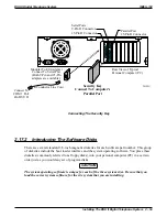
A green LED located on the common equipment cabinet is the system status indicator. This
indicator light comes on when power is supplied to the system. If the indicator flashes after
power up, it signals that the processor has failed or that the software is not operating. Unplug and
reconnect the AC power to the power supply and observe the LED indication. If it still shows a
flashing indication, equipment replacement may be necessary.
2.16.2
Testing The Stations
To test the multiline stations for proper operation:
1. Disconnect line cord at station base then reconnect it.
2. On DigiTech telephones, press and hold the
MUTE
button.
On Impact and Impression telephones, press and hold
1
on the keypad.
Station will automatically perform self test routine.
3. Release test button as soon as test begins. Sequence of test is as follows:
a. indicators will light in sequence,
b. ringer will sound—be sure volume is set to low or high,
c. indicators and ringer will then turn off at the same time.
4. Replace any station that does not pass the self test.
DSU II Digital Telephone System
IMI66–132
Installing The DSU II Digital Telephone System 2 – 51
Summary of Contents for DSU II
Page 31: ......


