Installation
SYSTEM WIRING
System cabling may be routed concealed or visible as the installation
location requires.
Good engineering practices must be observed and
all applicable building codes must be adhered to.
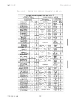
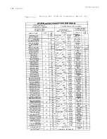
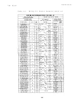
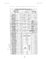
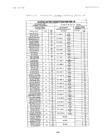
Tables 2-l through
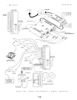
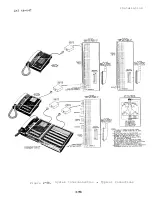
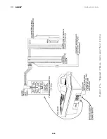
2-5 and Figures 2-2 through 2-5 illustrate the system wiring and
connection points.
AC Power Connection
-- ____
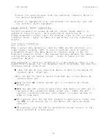
Connect the power interconnection cable between the power supply and
the KSU.
Do not connect or disconnect the power interconnection cable
while the AC power cord is connected to the AC outlet.
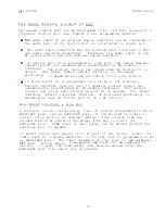
To apply AC power to the power supply,
connect the AC power cord to
the NEMA
outlet which supplies the dedicated 117VAC
15
AMP
electrical power.
A plug-in,
power line surge protector should be
installed between the KSU power cord and the AC outlet.
Line
Do not connect the AC power cord until the installation has
been checked per the SYSTEM CHECKOUT instructions given
later in this chapter.
Connections
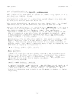
The KSU interface connection for the TELCO or PBX lines is a 50-pin,
male connector.
A 25-pair cable,
properly terminated, must be
connected from the KSU connector to the demarcation point connector
(typically a
connector).
To help insure that foreign voltages, which could appear on
the TELCO lines,
do not damage the system, verify that gas
discharge tubes or similar protection devices are installed,
and properly grounded,
in all connected TELCO lines.
Station Connections
Connections between the KSU and the stations are
typically
connector blocks which are cable connected to the KSU 50-pin
male connector.
The maximum distance allowed from the KSU to the
station is 1500 feet using
gauge, twisted-pair cable.
If spare conductors exist in the cables that are run between the
connector block and the station jacks,
it is a good practice to
connect them to earth ground.
Doing this may help prevent them from
inducing radio frequency and/or AC interference into the system.
Summary of Contents for Executech 2232
Page 2: ......
Page 3: ......
Page 4: ......
Page 5: ......
Page 6: ......
Page 25: ... IMI 66 047 Installation L Figure 2 4a System Interconnection Typical Connections 2 15a ...
Page 26: ...IN1 66 047 Installation 2 Figure 2 4b System Interconnection Typical Connections 2 15b ...
Page 27: ...IMI 66 047 Installation 2 16 ...
Page 28: ......
Page 61: ......
Page 71: ......
Page 75: ......
Page 79: ...COMDIAL Charlottesville Va 22901 PRINTED IN U S A 716604 700 01 ...
Page 80: ......


