IMI 66-047
Installation
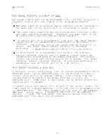
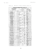
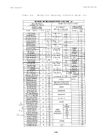
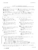
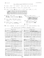
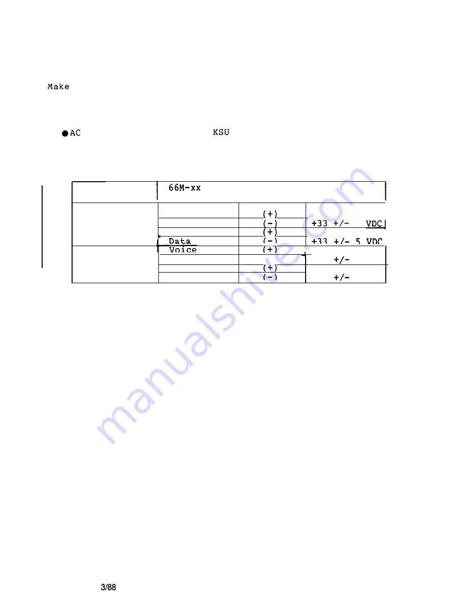
Voltage Check
the following voltage measurements at the station connector
blocks under the following conditions
l
Bridging clips installed
power connected to the
UNIT UNDER
BLOCK METER LEAD
I
I
MEASURED
TEST
CONNECTION
POLARITY
VOLTAGE
TYPICAL EVEN
STATION
Repeat for
each even sta.
TYPICAL ODD
STATION
Repeat for
each odd sta.
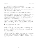
Measure the voltage across one voice line and one data line and then
across the other voice line and the other data line for each even and
odd station.
The measured voltage must be as follows:
, Voice 1
Data
3
I
Voice
2
5
4
I
----
i-i
Data
11
- 3 3
5
VDC
Voice
10
Data
12
- 3 3
5
VDC
Variant readings can indicate a possible wiring, station, or KSU
problem.
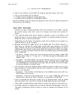
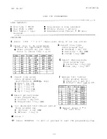
General Check
1 .
Check the red light emitting diode (LED) system status indicator.
Be sure that it is on steady.
If it is off or flashing,
disconnect and reconnect the AC power plug.
If the indicator is
still not on steady,
refer to the Failure Analysis Flow Chart
found in Chapter 4.
2 .
Refer to the station User's Guide for operating information.
Perform a general operational test of the system by exercising the
system features from station port 10 or 11.
Operational
parameters are per the system default conditions as detailed in
Chapter 3 until Class Of Service (COS) programming is performed.
3 .
Once the basic system is verified as operational, perform the COS
programming.
Change page
2-18
Summary of Contents for Executech 2232
Page 2: ......
Page 3: ......
Page 4: ......
Page 5: ......
Page 6: ......
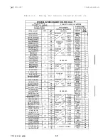
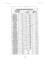
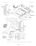
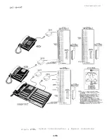
Page 25: ... IMI 66 047 Installation L Figure 2 4a System Interconnection Typical Connections 2 15a ...
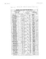
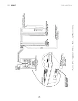
Page 26: ...IN1 66 047 Installation 2 Figure 2 4b System Interconnection Typical Connections 2 15b ...
Page 27: ...IMI 66 047 Installation 2 16 ...
Page 28: ......
Page 61: ......
Page 71: ......
Page 75: ......
Page 79: ...COMDIAL Charlottesville Va 22901 PRINTED IN U S A 716604 700 01 ...
Page 80: ......


