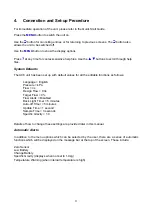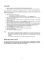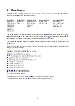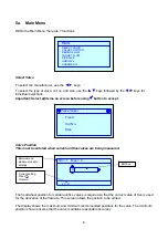
17
Using the SAVE command will overwrite the location with the current valve data.
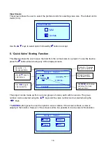
The Quick Valve feature allows the user to save the selected valve to a memory location which is
quickly accessible without having to use the ‘Select Valve’ option. The purpose of this is to reduce
time when commissioning a system with, for example, 3 different types of valve. The 3 types of
valve could be saved to the Quick Valve memory including the design flow designated for that valve.
When recalled, the valve will be loaded to the unit including the design flow.
Follow the on-screen instructions to save the current selection or delete the existing saved valve.
An additional use for this feature is the ability for the user to save the commissioned data for up to
100 valves for later reference.
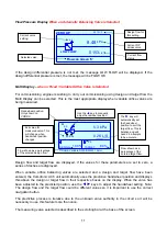
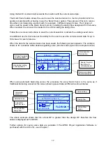
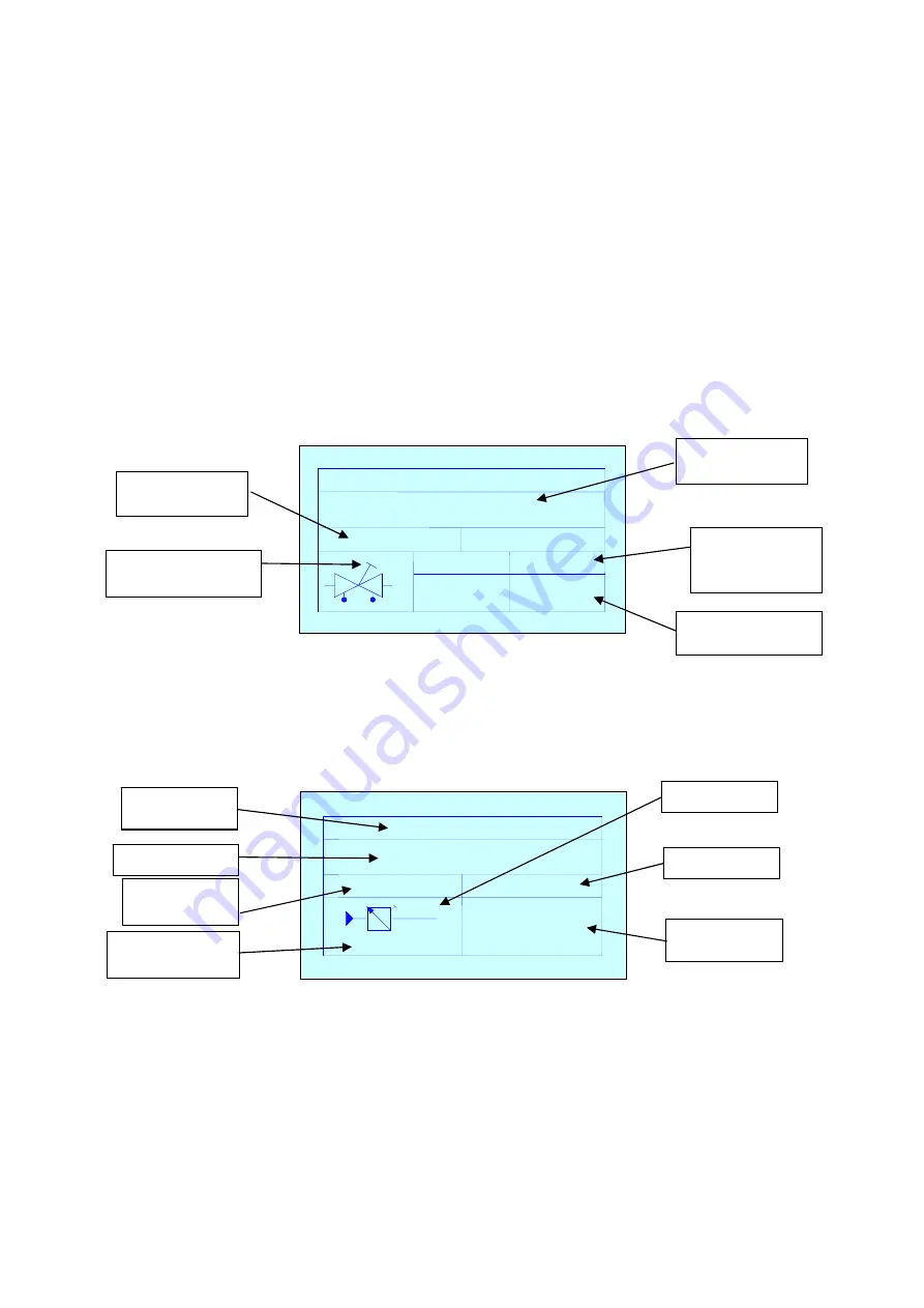
When the data for the selected valve has been saved, the following screen appears. The example
shown is for a variable orifice double-regulating valve (all other valve types have a simpler screen).
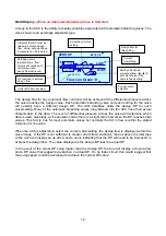
When using automatic balancing valves, the procedure for using ‘Quick Valve’ is the same as if
traditional balancing valves but the screen showing saved data is different as shown below.
The above example shows that the actual DP is greater than the design DP therefore the flow
status is displayed as FLOW OK.
Further options for saving valve data are available if PcomPRO Project Application Software is
purchased with the AC6 unit – see Chapter 7.
Group 1 Valve 1
19.23 kPa
0.487 l/s
Crane Variable D930DM930 15mm
DESIGN 244 %
TARGET 271 %
DESIGN FLOW
TARGET FLOW
0.2
90%
4
Valve saved to
this location.
DP and flow data
currently saved.
Design flow and
target flow %
currently saved.
Handwheel setting
currently saved.
Design and target
flow currently set.
Group 1 Valve 1
21.5 kPa
0.210 l/s
Flowcon green ‘0’
FLOW OK
5
16.00 kPa
Group and
valve No.
Selected valve.
Current flow
status.
Design flow.
Actual DP
across valve.
Valve setting.
DP required for
design flow.

