background image

ENGLISH

21

6


Operating guidelines

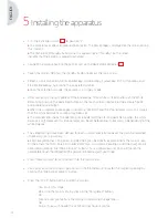
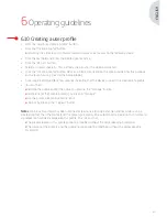
6.10 Creating a user profile

•  Click the “Log in or create a profile” button.
•  Click the “Create a profile” button.

 è

Activating the camera with a blank Smartcard gives direct access to the following stage.

•  Click the text field and enter the desired profile name.
•  Click the “Return” button.
•  Select a surgical specialty. This will form the basis for the video parameters.
•  Click the “Create a profile” button OR scan a blank Smartcard on the area provided for this purpose 

on the lexan housing (next to the Comeg logo).

•  A message is displayed for a few seconds indicating that the device supports the creation of a profile.
•  You can then:

 è

Rename the profile and/or the preset by clicking the “Manage” button.

 è

Delete one (of the) profile preset(s) by clicking “Manage”.

 è

Use the preset created by clicking on it.

 è

Log out by clicking the “Log out” button. 

Notes:


If a blank Smartcard has been scanned at least once (during activation and/or while saving a 

created profile), then the profile (and the presets) created will be automatically linked to this Smartcard.  
A padlock icon will be displayed on this profile. This means that:

è

The presets locked in this profile cannot be modified without the corresponding Smartcard. 

è

The names of the presets and the profile name cannot be modified without the corresponding  

Smartcard.

Summary of Contents for SYMBIOZ Cam+

Page 1: ...INTUITIVE CONNECTION Cam User manual Manuel utilisateur Manual del usuario Manuale utente Benutzerhandbuch Gebruikershandleiding Podr cznik u ytkownika...

Page 2: ...2...

Page 3: ...User manual 5 Manuel utilisateur 37 Manual del usuario 69 Manuale utente 101 Benutzerhandbuch 133 Gebruikershandleiding 165 Podr cznik u ytkownika 197 3 Cam...

Page 4: ...4...

Page 5: ...INTUITIVE CONNECTION English ENGLISH 5...

Page 6: ...ENGLISH 6 6...

Page 7: ...5 Installing the apparatus 13 6 Operating guidelines 16 7 Description of the front and back panels 22 8 Suggested decontamination procedures 24 9 After sales service and maintenance 26 10 Troubleshoot...

Page 8: ...symbol represent items of information To facilitate installation and use of the apparatus we have attempted to make the device manual more practical Consequently references to the product presentatio...

Page 9: ...y This camera comes with A control unit A camera head with integrated 15 35 mm zoom lens Video cables A power cable A peripheral cable Two communication SOPROCOM cables A set of 6 Smartcards A user ma...

Page 10: ...e of the camera can reach 41 C after a few minutes use Therefore avoid any contact with this area The camera is intended for use by qualified trained professionals in an operating theatre Prior to plu...

Page 11: ...evice is to be used on individuals patients fit to undergo an endoscopic procedure The potential equalization plug located at the back of the medical apparatus can be used to equalize the grounding po...

Page 12: ...arts Keep the apparatus away from electromagnetic sources e g compressors motors transformers HF generators etc 4 3Medicaldevicevigilance Like any medical device this apparatus is subject to the stipu...

Page 13: ...ded Connecting the endoscope to the sensor Turn the ring on the endoscope holder on the camera head clockwise Once the endoscope is inserted release the ring If the sensor has to be locked into positi...

Page 14: ...balance has successfully been set The chronometer shows the operating time by default the starting point being when the white balance is set However this chronometer can be set beforehand if necessar...

Page 15: ...Smartcard Activate the camera directly on the surgical screen in the surgical application corresponding to the Smartcard scanned Scanning a personal Smartcard Activate the camera directly on the surg...

Page 16: ...If you have entered customized parameters into a user profile beforehand then you can select this user profile either by using the Log in button or by scanning your personal Smartcard on the dedicated...

Page 17: ...2 Peripheral 2 Mirror Mirror Freeze frame Freeze frame Recording images on the camera if equipped with an integrated recorder AWB Record Stop video recording on the camera if equipped with an integrat...

Page 18: ...ty settings Note 2 If the light source is connected to the camera by the communication cable supplied then setting the white balance will cause the LED to light up if it was previously off In the even...

Page 19: ...sequence Start insufflation in low flow Change to high flow Stop insufflation BRIGHTNESS This parameter varies the general brightness of the image BLUE GAIN Colorimetry shift from white to blue RED G...

Page 20: ...settings on the surgical monitor supported models only Once the selection has been made you can overwrite the existing preset or create another one 6 7Generalsettingsmenu The general settings menu is...

Page 21: ...a few seconds indicating that the device supports the creation of a profile You can then Rename the profile and or the preset by clicking the Manage button Delete one of the profile preset s by click...

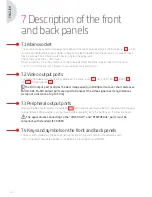
Page 22: ...6 HD SDI 3G SDI C8 RGBS C5 Y C C10 and composite C11 The DVI output port provides the best image quality in 1080p format over short distances HD SDI 3G SDI output ports are used to transport the video...

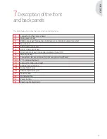
Page 23: ...n S1 Standby button S2 Power button Z1 Read area for Smartcard 7Descriptionofthefront andbackpanels The table below describes the back and front components C1 Connector for the Camera head C2 Main pow...

Page 24: ...alkaline solutions for the disinfection of certain medical devices are NOT RECOMMENDED for disinfecting this apparatus Disinfecting the camera head Any other disinfection methods are prohibited and th...

Page 25: ...cap can be immersed Traces of water are visible just as the connector seal is removed runoff and condensation It is therefore essential to dry the inside of the cap well before reusing it Disinfecting...

Page 26: ...a short explanatory note about the fault noted The equipment must be disinfected before it is returned for repair When returning the equipment check its condition and note any exceptions on the shippi...

Page 27: ...that the image settings are at the mid point position color light and contrast Check the light source the light cable and the endoscope 10 3Theimageisblurredandwhiteallover Check that there is no cond...

Page 28: ...note any exceptions on the shipping order if necessary and confirm these with the shipper by registered mail within 48 hours If any equipment shipped by us suffers damage during transport the total a...

Page 29: ...age humidity 20 to 85 Operating storage and transport atmospheric pressure 700 hPa to 1060 hPa Control unit is not drip proof IPXO Not suitable for use in the presence of a flammable anaesthetic mixtu...

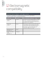
Page 30: ...ns CISPR 11 Group 1 This camera only uses radio energy for its internal functions Consequently its RF emissions are very weak and are not likely to interfere with nearby electronic equipment RF emissi...

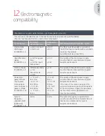
Page 31: ...l or typical hospital environment Electric shocks IEC 61000 4 5 Differential mode 1 kV Shared mode 2 kV 1 kV 2 kV The quality of the electric power supply must be that of a commercial or typical hospi...

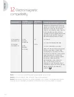
Page 32: ...33 P 800 MHz to 2 5 GHz Where P is the maximum output power from the transmitter in Watts W assigned by the manufacturer of the transmitter and d is the recommended separation distance in metres m The...

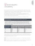
Page 33: ...tems cannot in theory be evaluated with accuracy To obtain an evaluation of the electro magnetic environment due to fixed RF transmitters measurements must be taken of the site If a field strength mea...

Page 34: ...or a neutral conductor for direct connection between the electrical equipment and the potential equalisation busbar Kindly refer to standard IEC 60601 1 3rd edition T UL CSA time delay fuses Video out...

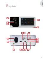
Page 35: ...ENGLISH 35 13Symbols C1 C14 L1 S1 Z1 C2 C5 C10 C11 C12 C13 S2 C6 C3 C4 C7 C9 C8...

Page 36: ...36...

Page 37: ...INTUITIVE CONNECTION Fran ais FRAN AIS 37...

Page 38: ...FRAN AIS 38 38...

Page 39: ...tallation de l appareil 45 6 Instructions d utilisation 48 7 Description des panneaux avant et arri re 54 8 Proc dures de d contamination recommand es 56 9 Service apr s vente et maintenance 58 10 D p...

Page 40: ...de faciliter l installation et l utilisation de l appareil nous avons essay de simplifier autant que possible le manuel Par cons quent des r f rences la page de pr sentation du produit en page 67 par...

Page 41: ...ou flexible La cam ra est livr e avec Une unit de contr le Une t te de cam ra avec objectif zoom 15 35 mm int gr Des c bles vid o Un c ble d alimentation Un c ble pour p riph rique Deux c bles de com...

Page 42: ...st rile La temp rature de surface de la cam ra peut atteindre 41 C apr s quelques minutes d utilisation vitez par cons quent tout contact avec cette zone La cam ra a t con ue pour tre utilis e dans u...

Page 43: ...it tre utilis sur des personnes patients en tat de passer un examen endoscopique La prise d quilibrage de tension situ e l arri re de l appareil m dical peut tre utilis e pour quilibrer la tension de...

Page 44: ...s appareils des sources lectromagn tiques par exemple compresseurs moteurs trans formateurs g n rateurs HF etc 4 3Vigilancerelativeauxdispositifsm dicaux Comme tout dispositif m dical cet appareil est...

Page 45: ...les deux c bles fournis Pour connecter l endoscope au capteur Tournez la bague du support de l endoscope de la t te de cam ra dans le sens horaire Une fois l endoscope ins r rel chez la bague Si le c...

Page 46: ...onctionnement par d faut le point de d part correspondant au moment o la balance des blancs est configur e Cependant ce chronom tre peut tre d clench pr alablement si n cessaire ind pendamment de la b...

Page 47: ...d une Smartcard Activez la cam ra directement sur l cran chirurgical dans l application chirurgicale correspondant la Smartcard scann e Scan d une Smartcard personnelle Activez la cam ra directement...

Page 48: ...alable des param tres personnalis s dans un profil utilisateur vous pouvez ensuite s lectionner ce profil utilisateur en appuyant sur le bouton Log in Connexion ou en scannant votre Smartcard personne...

Page 49: ...ement des images dans la cam ra si celle ci est quip e d un enregistreur int gr Balance des blancs automatique Enregistrement Arr t de l enregistrement vid o sur la cam ra si celle ci est quip e d un...

Page 50: ...a source de lumi re est connect e la cam ra l aide du c ble de communication fourni le r glage de la balance des blancs entra ne l activation de la LED au cas o elle serait teinte Si le r glage de la...

Page 51: ...ioz Flow selon la s quence suivante D marrer l insufflation bas d bit Passer en d bit lev Arr ter l insufflation LUMINOSIT Ce param tre permet de modifier la luminosit g n rale de l image GAIN BLEU Tr...

Page 52: ...cations apport es aux param tres du moniteur chirurgical uniquement pour les mod les compatibles Une fois la s lection effectu e vous pouvez craser le pr r glage existant ou en cr er un nouveau 6 7Men...

Page 53: ...ant quelques secondes indiquant que l appareil accepte la cr ation d un profil Vous pouvez alors Renommer le profil et ou le pr r glage en cliquant sur le bouton Manage G rer Supprimer un des profils...

Page 54: ...RGBS C5 Y C C10 et composite C11 Le port de sortie DVI offre la meilleure qualit d image en 1080p sur de courtes distances Les ports de sortie HD SDI et 3G SDI sont utilis s pour transmettre le signa...

Page 55: ...errupteur d alimentation Z1 Zone de lecture pour Smartcard 7Descriptiondespanneaux avantetarri re Le tableau ci dessous d crit les l ments des panneaux avant et arri re C1 Connecteur pour la t te de c...

Page 56: ...n d pend des produits des m thodes et ou des ustensiles utilis s le personnel concern est seul responsable de la d contamination L appareil doit toujours tre d connect avant toute proc dure de nettoya...

Page 57: ...trait du bouchon d tanch it dues au ruissellement et la conden sation Il est par cons quent primordial de bien s cher l int rieur du bouchon avant de le r utiliser D sinfection de la surface des objec...

Page 58: ...uillez joindre au bon d exp dition une note expliquant le probl me observ L quipement doit tre d sinfect avant d tre retourn pour r paration Lorsque vous retournez l quipement v rifiez son tat le cas...

Page 59: ...sont en position interm diaire couleur luminosit et contraste V rifiez la source de lumi re le c ble de la source de lumi re et l endoscope 10 3L imageestfloueettr sp le V rifiez qu il n y ait pas de...

Page 60: ...omalie sur le bon d exp dition le cas ch ant Confirmez ces anomalies au transporteur par courrier recommand sous 48 heures Si un quipement exp di par nos soins subit des dommages pendant le transport...

Page 61: ...de fonctionnement de transport et de stockage 700 hPa 1060 hPa L unit de contr le n est pas tanche au ruissellement d eau IPX0 Ne convient pas pour une utilisation en pr sence d un m lange anesth sia...

Page 62: ...ette cam ra utilise l nergie radio uniquement pour ses fonctions internes Par cons quent ses missions RF sont tr s faibles et ne sont donc pas susceptibles de cr er des interf rences avec les quipemen...

Page 63: ...ironnement hospitalier typique Chocs lectriques IEC 61000 4 5 Mode diff rentiel 1 kV Mode partag 2 kV 1 kV 2 kV La qualit de l alimentation lectrique doit tre celle d un environnement commercial ou d...

Page 64: ...nd e d 1 16 P d 1 16 P 80 MHz 800 MHz d 2 33 P 800 MHz 2 5 GHz P correspond la puissance de sortie maximale exprim e en watts W affect e l metteur par le fabricant et d correspond la distance de s par...

Page 65: ...alu e avec pr cision Afin d obtenir une valuation de l environnement lectromagn tique g n r par des metteurs RF fixes des mesures doivent tre effectu es sur site Si l intensit d un champ magn tique d...

Page 66: ...conducteur neutre pour une connexion directe entre l quipement lectrique et le jeu de barres d galisation des potentiels Veuillez vous reporter la norme IEC 60601 1 3e dition Fusibles temporis s T UL...

Page 67: ...67 FRAN AIS 13Symboles C1 C14 L1 S1 Z1 C2 C5 C10 C11 C12 C13 S2 C6 C3 C4 C7 C9 C8...

Page 68: ...68...

Page 69: ...INTUITIVE CONNECTION Espa ol ESPA OL 69...

Page 70: ...70 ESPA OL 70...

Page 71: ...taci n 76 5 Instalaci n del aparato 77 6 Instrucciones de uso 80 7 Descripci n de los paneles frontal y posterior 86 8 Procedimientos de descontaminaci n 88 9 Servicio posventa y mantenimiento 90 10 R...

Page 72: ...ato hemos intentado que este manual resulte lo m s pr ctico posible As paralocalizar m s f cilmente cada componente del producto se proporcionan en el texto referencias por ejemplo C1 que remiten a la...

Page 73: ...ye Una unidad de control Un cabezal con objetivo integrado de 15 35 mm Cables de v deo Un cable de alimentaci n Un cable perif rico Dos cables de comunicaci n SOPROCOM Un juego de 6 tarjetas inteligen...

Page 74: ...atura de la superficie de la c mara puede alcanzar 41 C despu s de unos minutos de uso por lo que debe evitar el contacto con esta zona La c mara debe ser utilizada exclusivamente en el quir fano por...

Page 75: ...acientes que est n en condiciones de someterse a procedimientos endosc picos El compensador de potencia situado en la parte posterior del aparato se puede utilizar para ecualizar el potencial de tierr...

Page 76: ...tenga el aparato alejado de las fuentes electromagn ticas por ejemplo compresores motores transformadores generadores de alta frecuencia etc 4 3Controldeldispositivom dico Como cualquier dispositivo m...

Page 77: ...re a la derecha el anillo del soporte del endoscopio en el cabezal de la c mara Una vez insertado el endoscopio suelte el anillo Si el sensor debe fijarse en su posici n en el endoscopio se deber gira...

Page 78: ...empo de funcionamiento predefinido el punto de partida es el ajuste del balance de blancos No obstante este cron metro se puede configurar antes si es necesario independientemente del balance de blanc...

Page 79: ...est ndar Active la c mara directamente en la pantalla quir rgica en la aplicaci n quir rgica correspondiente a la Smartcard escaneada Escanear una Smartcard personal Active la c mara directamente en...

Page 80: ...introducido de antemano par metros personalizados en un perfil de usuario puede seleccionar este perfil de usuario ya sea mediante el bot n Log in Iniciar sesi n o escaneando su Smartcard personal en...

Page 81: ...n Congelaci n de imagen Grabar im genes en la c mara si est equipada con un grabador integrado AWB Grabar Detener grabaci n de v deo de la c mara si est equipada con un grabador integrado Insuflador A...

Page 82: ...de imagen Nota 2 Si la fuente de iluminaci n est conectada a la c mara mediante el cable de comunicaci n suministrado al ajustar el balance de blancos se iluminar el LED si estaba apagado En caso de q...

Page 83: ...acuerdo con la siguiente secuencia Iniciar la insuflaci n con flujo bajo Cambiar a flujo alto Detener insuflaci n BRILLO Este par metro modifica el brillo general de la imagen GANANCIA DE AZUL Cambio...

Page 84: ...r rgico solo para los modelos compatibles Cuando haya efectuado la selecci n podr modificar el ajuste predefinido o crear uno nuevo 6 7Men ajustesgenerales El men de ajustes generales se utiliza para...

Page 85: ...egundos indicando que el dispositivo permite la creaci n de un perfil Aqu podr Asignar un nuevo nombre al perfil y o el ajuste predefinido haciendo clic en el bot n Manage Gesti n Eliminar uno de los...

Page 86: ...3G SDI C8 RGBS C5 Y C C10 y compuesto C11 El puerto de salida DVI proporciona la mejor calidad de imagen en formato 1080p en distancias cortas Los puertos de salida HD SDI 3G SDI se utilizan para tran...

Page 87: ...espera S2 Bot n de encendido Z1 rea de lectura para la Smartcard 7Descripci ndelospaneles frontalyposterior La siguiente tabla describe los componentes frontales y posteriores C1 Conector para el cab...

Page 88: ...Como la descontaminaci n depende de los m todos herramientas y o productos utilizados es responsabilidad exclusiva del personal correspondiente El aparato debe desconectarse siempre antes de cualquier...

Page 89: ...en quedar gotas de agua cuando se retira la tapa del conector escorrent a y condensaci n por lo que es esencial secar el interior de la misma antes de volver a usarla Desinfecci n de la superficie del...

Page 90: ...aver a constatada El equipo debe desinfectarse antes de ser enviado al servicio de reparaci n Para devolver el equipo compruebe su estado y si es necesario indique cualquier alteraci n en la orden de...

Page 91: ...do conectado a la entrada de v deo adecuada y que los ajustes de la imagen est en la posici n del medio color luz y contraste Compruebe la fuente de iluminaci n el cable de luz y el endoscopio 10 3Lai...

Page 92: ...es necesario indique cualquier alteraci n en la orden de env o y conf rmela con el transportista por correo certificado en un plazo m ximo de 48 horas Si un equipo sufre da os durante el transporte e...

Page 93: ...resi n atmosf rica de funcionamiento almacenamiento y transporte 700 hPa a 1060 hPa La unidad de control no est fabricada a prueba de goteo IPXO Equipo no apto para usar en presencia de mezclas anest...

Page 94: ...11 Grupo 1 Esta c mara solo utiliza energ a de radiofrecuencia para sus funciones internas Por lo tanto sus emisiones de RF son muy bajas y no es probable que causen interferencias con equipos electr...

Page 95: ...a de un entorno comercial u hospitalario est ndar Descargas el ctricas IEC 61000 4 5 Modo diferencial 1 kV Modo compartido 2 kV 1 kV 2 kV La calidad del suministro el ctrico debe ser la de un entorno...

Page 96: ...GHz Donde P es la potencia de salida m xima del transmisor en vatios W indicada por el fabricante del transmisor y d la separaci n recomendada en metros m Las intensidades de campo emitidas por transm...

Page 97: ...pueden evaluar con precisi n Para obtener una evaluaci n del entorno electromagn tico generado por transmisores de RF deben realizarse mediciones en el establecimiento Si una intensidad de campo medid...

Page 98: ...onexi n directa entre el equipo el ctrico y la barra conductora de compensaci n de potencial Consulte la publicaci n IEC 60601 1 3 edici n Intervalo de tiempo T UL CSA Puertos de salida de v deo y per...

Page 99: ...99 ESPA OL 13S mbolos C1 C14 L1 S1 Z1 C2 C5 C10 C11 C12 C13 S2 C6 C3 C4 C7 C9 C8...

Page 100: ...100...

Page 101: ...INTUITIVE CONNECTION Italiano ITALIANO 101...

Page 102: ...102 ITALIANO 102...

Page 103: ...Installazione del dispositivo 109 6 Linee guida operative 112 7 Descrizione del pannello frontale e posteriore 118 8 Procedure di decontaminazione suggerite 120 9 Assistenza post vendita e manutenzion...

Page 104: ...facilitare l installazione e l uso del dispositivo abbiamo cercato di rendere questo manuale il pi pratico possibile Perci nella presentazione del prodotto a pagina 131 vengono forniti dei riferimenti...

Page 105: ...it di controllo Una testa videocamera con lenti zoom da 15 35 mm Cavi video Cavo di alimentazione Cavo di collegamento periferiche Due cavi di comunicazione SOPROCOM Una serie di 6 Smartcard Un manual...

Page 106: ...1 C dopo alcuni minuti di funzionamento Pertanto evitare qualsiasi contatto con quest area La videocamera progettata per essere utilizzata da professionisti qualificati e preparati in sala operatoria...

Page 107: ...etti pazienti in grado di affrontare una procedura endoscopica La presa equipotenziale posta sul retro del dispositivo medico pu essere utilizzata per equalizzare il potenziale della messa a terra del...

Page 108: ...relli medicali Conservare il dispositivo lontano da fonti elettromagnetiche quali compressori motori trasformatori generatori HF ecc 4 3Vigilanzasuidispositivimedici Come tutti i dispositivi medici qu...

Page 109: ...Collegamento dell endoscopio al sensore Ruotare l anello sul supporto dell endoscopio sulla testa della videocamera in senso orario Una volta inserito l endoscopio rilasciare l anello Se necessario b...

Page 110: ...ente il tempo dell operazione partendo dal momento in cui viene eseguito il bilanciamento del bianco Tuttavia se necessario il cronometro pu anche essere preventivamente impostato indipendentemente da...

Page 111: ...ideocamera direttamente sullo schermo chirurgico nell applicazione chirurgica corrispondente alla Smartcard che si vuole leggere Scansione di una Smartcard personale Attivare la videocamera direttamen...

Page 112: ...i precedentemente inseriti dei parametri personalizzati in un profilo utente possibile selezionare quel profilo usando il pulsante Log in Accedi o eseguendo la scansione della Smartcard personale sull...

Page 113: ...ermo immagine Registrazione delle immagini sulla videocamera se dotata di registratore integrato AWB Registrazione Interruzione registrazione video sulla videocamera se dotata di un registratore integ...

Page 114: ...della qualit delle immagini Nota 2 Se la sorgente luminosa collegata alla videocamera tramite il cavo di comunicazione fornito l impostazione del bilanciamento del bianco far accendere il LED se prim...

Page 115: ...Inizio insufflazione con flusso basso Passa a flusso alto Interrompi insufflazione LUMINOSIT Questo parametro varia la luminosit generale dell immagine BLUE GAIN La colorimetria passa dal bianco al bl...

Page 116: ...i modelli supportati Dopo aver effettuato la scelta possibile sovrascrivere le impostazioni predefinite esistenti o crearne di nuove 6 7Menuimpostazionigenerali Il menu delle impostazioni generali vi...

Page 117: ...l dispositivo supporta la creazione di un profilo A questo punto possibile Rinominare il profilo e o l impostazione predefinita facendo clic sul pulsante Manage Gestisci Cancellare una delle impostazi...

Page 118: ...li le seguenti uscite video DVI C6 HD SDI 3G SDI C8 RGBS C5 Y C C10 e composito C11 L uscita DVI fornisce la migliore qualit dell immagine in formato 1080p sulle brevi distanze Le uscite HD SDI 3G SDI...

Page 119: ...censione Z1 Area di lettura per Smartcard 7Descrizionedelpannello frontaleeposteriore La tabella che segue descrive gli elementi presenti sul fronte e sul retro C1 Connettore per la testa della videoc...

Page 120: ...ontaminazione dipende dai prodotti dai metodi e o dagli strumenti utilizzati la de contaminazione di esclusiva responsabilit del personale interessato Il dispositivo deve sempre essere scollegato prim...

Page 121: ...rimosso sono visibili tracce d acqua deflusso o condensa pertanto essenziale asciugare accuratamente l interno del cappuccio prima di riutilizzarlo Disinfezione delle superfici delle lenti Lo sporco...

Page 122: ...reve nota che descriva il problema riscontrato Prima della restituzione per la riparazione il dispositivo deve essere disinfettato Quando si restituisce il dispositivo verificarne le condizioni e anno...

Page 123: ...e le impostazioni dell immagine siano a met colore luce e contrasto Verificare la sorgente luminosa il cavo dell illuminazione e l endoscopio 10 3L immagine confusaebianca Verificare che non ci sia de...

Page 124: ...e tutte le discrepanze sull ordine di spedizione se necessario e confermarle al trasportatore tramite lettera raccomandata entro 48 ore Se un dispositivo spedito da noi dovesse subire dei danni durant...

Page 125: ...85 Pressione atmosferica durante il funzionamento la conservazione e il trasporto da 700 hPa a 1 060 hPa L unit di controllo non resistente alle gocce IPXO Non adatto all utilizzo in presenza di misc...

Page 126: ...Questa videocamera utilizza energia in radiofrequenza solo per il suo funzionamento interno Di conseguenza le sue emissioni RF sono molto ridotte e tali da comportare bassi rischi d interferenza con e...

Page 127: ...tipiche applicazioni commerciali od ospedaliere Shock elettrici IEC 61000 4 5 Modalit differenziale 1 kV Modalit comune 2 kV 1 kV 2 kV La qualit dell alimentazione elettrica deve essere quella delle t...

Page 128: ...2 33 P 800 MHz a 2 5 GHz Laddove P la potenza massima in uscita del trasmettitore espressa in watt W stabilita dal fabbricante e d la distanza di separazione consigliata in metri m L intensit dei cam...

Page 129: ...ti televisive non possono essere previsti con precisione su base teorica Per la valutazione dell ambiente elettromagnetico creato da trasmettitori RF fissi necessario eseguire una misurazione in loco...

Page 130: ...neutro per il collegamento diretto tra il dispositivo elettrico e il bus bar per l equalizzazione del potenziale Fare riferimento allo standard IEC 60601 1 IIIa edizione Fusibili ritardati T UL CSA P...

Page 131: ...131 ITALIANO 13Simboli C1 C14 L1 S1 Z1 C2 C5 C10 C11 C12 C13 S2 C6 C3 C4 C7 C9 C8...

Page 132: ...132...

Page 133: ...INTUITIVE CONNECTION Deutsch DEUTSCH 133...

Page 134: ...134 DEUTSCH 134...

Page 135: ...140 5 Installation des Ger ts 141 6 Betriebsrichtlinien 144 7 Beschreibung der Vorder und R ckblenden 150 8 Empfohlene Verfahren zur Dekontamination 152 9 Kundendienst und Wartung 154 10 Probleml sung...

Page 136: ...tieren Informationen Zur Erleichterung der Installation und des Gebrauchs des Ger ts haben wir alles unternommen um das Ger t praktischer zu gestalten Dementsprechend finden Sie Verweise auf die Produ...

Page 137: ...kopie Zu dieser Kamera geh ren Eine Bedieneinheit Ein Kamerakopf mit integriertem 15 35 mm Zoomobjektiv Mehrere Videokabel Ein Netzkabel Ein Peripheriekabel Zwei Kommunikationskabel SOPROCOM Ein Satz...

Page 138: ...hentemperatur der Kamera kann 41 C erreichen nach einigen Minuten in Betrieb Vermeiden Sie daher jeglichen Kontakt mit diesem Bereich Diese Kamera ist f r den Gebrauch durch qualifizierte geschulte Fa...

Page 139: ...ersonen Patienten bestimmt bei denen eine endoskopische Untersuchung ohne Bedenken durchgef hrt werden kann Der Potenzialausgleichsanschluss auf der R ckseite des Medizinprodukts kann f r den Ausgleic...

Page 140: ...die Erdung aller Ger te und Medizinwagen Sie das Ger t von elektromagnetischen Quellen z B Kompressoren Motoren Transformatoren HF Generatoren usw fernhalten 4 3 berwachungssystemf rMedizinprodukte W...

Page 141: ...Sensor Drehen Sie den Ring an der Endoskop Halterung des Kamerakopfs im Uhrzeigersinn Sobald das Endoskop eingesetzt ist lassen Sie den Ring los Wenn der Sensor am Endoskop in seine Stellung eingeras...

Page 142: ...tartpunkt entspricht dem Abschluss des Wei abgleichs Dieses Chronometer kann aber unabh ngig von dem Wei abgleich fr her gestartet werden Die Videoeinstellungen sind f r jede chirurgische Fachrichtung...

Page 143: ...e Kamera direkt auf dem OP Bildschirm in der chirurgischen Anwendung die der gescannten Smartcard entspricht So scannen Sie eine pers nliche Smartcard Aktivieren Sie die Kamera direkt auf dem OP Bilds...

Page 144: ...profil vorher bereits benutzerdefinierte Parameter eingegeben haben k nnen Sie dieses Benutzerprofil entweder durch den Knopf Log in Anmelden aufrufen oder durch Einscannen Ihrer pers nlichen Smartcar...

Page 145: ...der Kamera aufnehmen falls sie mit einem integrierten Aufzeichnungsger t ausgestattet ist AWB Video Aufzeichnung mit der Kamera starten stoppen falls sie mit einem integrierten Aufzeichnungsger t aus...

Page 146: ...stellungen der Bildqualit t verbunden sind Hinweis 2 Falls die Lichtquelle ber das mitgelieferte Kommunikationskabel mit der Kamera verbunden ist leuchtet beim Wei abgleich die LED auf sofern sie vorh...

Page 147: ...uss Wechsel nach hohem Durchfluss Stopp der Insufflation HELLIGKEIT Dieser Parameter ver ndert die allgemeine Helligkeit des Bildes BLAU VERST RKUNG Kolometrie Verschiebung von Wei nach Blau ROT VERST...

Page 148: ...OP Monitor nur unterst tzte Modelle Sobald die Auswahl getroffen wurde k nnen Sie die bestehende Voreinstellung berschreiben oder eine neue erstellen 6 7Men allgemeineEinstellungen Das Men mit den al...

Page 149: ...ird f r ein paar Sekunden eine Meldung angezeigt die besagt dass das Ger t das Erstellen eines Profils unterst tzt Danach k nnen Sie Das Profil und oder die Voreinstellung ber den Knopf Manage Verwalt...

Page 150: ...ra enthalten DVI C6 HD SDI 3G SDI C8 RGBS C5 Y C C10 und Composite C11 Der DVI Ausgang liefert die beste Bildqualit t im 1080p Format auf kurze Entfernungen HD SDI und 3G SDI Ausg nge werden f r die b...

Page 151: ...tandby Knopf S2 Netzschalter Z1 Lesebereich f r die Smartcard 7Beschreibungder Vorder undR ckblenden In der folgenden Tabelle werden die Komponenten auf der Vorder und R ckseite beschrieben C1 Anschlu...

Page 152: ...die Dekontamination mit den verwendeten Produkten Methoden und oder Werkzeugen verkn pft ist liegt die Verantwortung f r die Dekontamination einzig und allein beim zust ndigen Personal Das Ger t muss...

Page 153: ...er Dichtung des Verbinders Wasserspuren auftreten Ablauf und Kondensation Daher muss die Innenseite der Kappe vor erneutem Gebrauch getrocknet werden Desinfektion der Linsenoberfl chen Eine schmutzige...

Page 154: ...Fehlers bei Die Ausr stung muss vor dem Versand zur Reparatur desinfiziert werden Bei Erhalt des Ger ts pr fen Sie seinen Zustand und notieren Sie ggf jegliche Auff lligkeiten in dem Versandauftrag u...

Page 155: ...eit und Kontrast sich in der Mittelstellung befinden Pr fen Sie die Lichtquelle das Lichtkabel und das Endoskop 10 3DasBildistunscharfundfastkomplettweiss Pr fen Sie ob sich auf der Linse Kondensat ge...

Page 156: ...trag und best tigen diese mit dem Spediteur durch Einschreiben innerhalb von 48 Stunden Falls irgendein Ger t dass von uns verschickt wurde w hrend des Transports einen Schaden erleidet werden die Kos...

Page 157: ...uck f r Betrieb Lagerung und Transport 700 hPa bis 1060 hPa Die Bedieneinheit ist nicht tropfwassergesch tzt IPXO Das Ger t ist nicht geeignet f r die Verwendung bei Vorhandensein von entflammbaren An...

Page 158: ...Emissionen CISPR 11 Gruppe 1 Diese Kamera nutzt HF Energie nur f r ihre internen Funktionen Deshalb ist die abgegebene HF Strahlung sehr gering und es ist unwahrscheinlich dass die unmittelbare elektr...

Page 159: ...ypischen Gesch ftsumgebung oder einer Krankenhausumgebung entsprechen Elektrischer Schlag IEC 61000 4 5 1 kV Differenzial Modus 2 kV Gemeinsamer Modus 1 kV 2 kV Die Qualit t der elektrischen Stromvers...

Page 160: ...d 2 33 P 800 MHz bis 2 5 GHz Wobei P die maximale Ausgangsleis tung des Senders in Watt W nach Angabe des Senderherstellers und d der empfohlene Abstand in Metern m ist Die Feldst rke von festste hen...

Page 161: ...kationssysteme und Fernsehsysteme kann theoretisch nicht genau ermittelt werden Zur Beurteilung der elektromagnetischen Umgebung mit feststehenden Sendern m ssen vor Ort Messungen vorgenommen werden W...

Page 162: ...ung der elektrischen Ausr stung mit der Potenzialausgleichs Stromschiene Bitte beachten Sie die Norm IEC 60601 1 3 Ausgabe T UL CSA Sicherungen mit Zeitverz gerung Videoausg nge und Peripheriesteuerun...

Page 163: ...163 DEUTSCH 13Symbole C1 C14 L1 S1 Z1 C2 C5 C10 C11 C12 C13 S2 C6 C3 C4 C7 C9 C8...

Page 164: ...164...

Page 165: ...INTUITIVE CONNECTION Nederlands NEDERLANDS 165...

Page 166: ...166 NEDERLANDS 166...

Page 167: ...5 Installatie van het apparaat 173 6 Bedieningsrichtlijnen 176 7 Beschrijving van de voor en achterpanelen 182 8 Aanbevolen ontsmettingsmethoden 184 9 Aftersales en onderhoud 186 10 Probleemoplossing...

Page 168: ...items met informatie Om de installatie en het gebruik van het apparaat te vergemakkelijken hebben we geprobeerd de handleiding praktischer te maken Daarom worden verwijzingen gegeven naar de productpr...

Page 169: ...met Een bedieningseenheid Een camerakop met ge ntegreerde 15 35 mm zoomlens Videokabels Een voedingskabel Een randapparatuurkabel Twee communicatiekabels Soprocom Een set van 6 Smartcards Een gebruike...

Page 170: ...rvlaktetemperatuur van de camera kan 41 C bereiken na enkele minuten gebruik Vermijd daarom elk contact met dit gebied De camera is bedoeld voor gebruik door gekwalificeerde opgeleide professionals in...

Page 171: ...rdt gebruikt bij individuen pati nten die in staat zijn om een endoscopische procedure te ondergaan De potentiaalvereffeningsstekker aan de achterkant van het medische apparaat kan worden gebruikt om...

Page 172: ...raat uit de buurt te houden van elektromagnetische bronnen zoals compressoren motoren transformatoren HF generatoren etc 4 3Toezichtopmedischehulpmiddelen Zoals alle medische apparatuur is dit apparaa...

Page 173: ...geleverde kabels De endoscoop aansluiten op de sensor Draai de ring op de endoscoop houder op de camerakop rechtsom Laat de ring los zodra de endoscoop is geplaatst Indien de sensor moet worden vastge...

Page 174: ...ijfstijd weer met als startpunt het moment waarop de witbalans is ingesteld Indien nodig kan de chronometer echter op voorhand worden ingesteld onafhankelijk van de witbalans De video instellingen zij...

Page 175: ...rtcard Activeer de camera rechtstreeks op het chirurgische scherm in de chirurgische toepassing die overeenkomt met de gescande Smartcard Scannen van een persoonlijke Smartcard Activeer de camera rech...

Page 176: ...king 2 Als u voorafgaand aangepaste parameters in een gebruikersprofiel hebt ingevoerd dan kunt u dit gebruikersprofiel selecteren met behulp van de knop Log in aanmelden of door uw persoonlijke Smart...

Page 177: ...l Spiegel Beeld stilzetten Beeld stilzetten Beelden opnemen op de camera indien uitgerust met een ingebouwde recorder AWB Opnemen stoppen met opnemen van videobeelden op de camera indien uitgerust met...

Page 178: ...gen voor de beeldkwaliteit Opmerking 2 Als de lichtbron is verbonden met de camera via de meegeleverde kabel dan zal het instellen van de witbalans ervoor zorgen dat de LED gaat branden als deze eerde...

Page 179: ...en op lage snelheid Wijzig naar hoge snelheid Stop inblazen HELDERHEID Deze parameter regelt de algemene helderheid van het beeld BLAUWVERSTERKING Colorimetrie verschuiving van wit naar blauw ROODVERS...

Page 180: ...de modellen Nadat de selectie is gemaakt kunt u de bestaande voorinstelling overschrijven of een nieuwe aanmaken 6 7Menualgemeneinstellingen Het menu algemene instellingen wordt gebruikt om De lichtin...

Page 181: ...at het apparaat het aanmaken van een profiel ondersteunt Vervolgens kunt u Het profiel en of de voorinstelling hernoemen door te klikken op de knop Manage Beheren n van de voorinstelling en verwijdere...

Page 182: ...6 HD SDI 3G SDI C8 RGBS C5 Y C C10 en composiet C11 De DVI uitgang biedt de beste beeldkwaliteit in 1080p formaat over korte afstanden De uitgangen HD SDI 3G SDI worden gebruikt om het videosignaal ov...

Page 183: ...Standby knop S2 Aanknop Z1 Leesgebied voor Smartcard 7Beschrijvingvande voor enachterpanelen In de onderstaande tabel worden de onderdelen aan de voor en achterkant omschreven C1 Connector voor de cam...

Page 184: ...tsmetting afhankelijk is van de producten methoden en of instrumenten die worden gebruikt is ontsmetting de verantwoordelijkheid van het betrokken personeel Het apparaat moet altijd worden losgekoppel...

Page 185: ...water zijn zichtbaar als de connectorafdichting wordt verwijderd afstroming en condensatie Het is daarom noodzakelijk om de binnenkant van de kap goed te drogen alvorens deze opnieuw wordt gebruikt On...

Page 186: ...voordat deze wordt teruggestuurd voor reparatie Controleer bij terugsturen de staat en noteer eventuele bijzonderheden op de verzendopdracht en laat deze binnen 48 uur per aantegekende post door de k...

Page 187: ...ingang is aangesloten en of de beeldinstellingen op de middenpositie staan kleur licht en contrast Controleer de lichtbron de lichtkabel en de endoscoop 10 3Hetbeeldiswazigeniscompleetwit Controleer o...

Page 188: ...op de verzendopdracht en laat deze binnen 48 uur per aangetekende post door de koeriersdienst bevestigen Als door ons verscheepte apparatuur schade ondervindt tijdens het transport zal het totale bedr...

Page 189: ...tmosferische druk bediening opslag en transport 700 hPa tot 1060 hPa Bedieningseenheid is niet druipwaterdicht IPXO Niet geschikt voor gebruik in aanwezigheid van een ontvlambaar narcotisch mengsel me...

Page 190: ...sies CISPR 11 Groep 1 Deze camera maakt alleen gebruik van radio energie voor zijn interne functies Bijgevolg zijn de RF emissies zeer zwak en is het onwaarschijnlijk dat deze interfereren met nabijge...

Page 191: ...n commerci le omgeving of typische ziekenhuisomgeving Elektrische schokken IEC 61000 4 5 Differenti le modus 1 kV Gedeelde modus 2 kV 1 kV 2 kV De kwaliteit van de netspanning moet overeenkomen met di...

Page 192: ...2 5 GHz Waarbij P het maximale uitgangs vermogen van de zender in Watt W is toegewezen door de fabrikant van de zender en d de aanbevolen afstand in meters m De uitgezonden veldsterktes door vaste RF...

Page 193: ...keurig worden ge valueerd Om de invloed van vaste RF zenders op de elektromagnetische omgeving te beoordelen moeten de metingen worden gedaan op locatie Als een gemeten veldsterkte in de omgeving waar...

Page 194: ...e geleider voor een rechtstreekse verbinding tussen de elektrische apparatuur en de potentiaalvereffeningsaardrail Raadpleeg norm CEI 60601 1 3e editie T UL CSA vertraagde zekeringen Video uitgangen e...

Page 195: ...195 NEDERLANDS 13Symbolen C1 C14 L1 S1 Z1 C2 C5 C10 C11 C12 C13 S2 C6 C3 C4 C7 C9 C8...

Page 196: ...196...

Page 197: ...INTUITIVE CONNECTION Polski POLSKI 197...

Page 198: ...198 POLSKI 198...

Page 199: ...ulacyjne 204 5 Instalacja urz dzenia 205 6 Wskaz wki dot obs ugi 208 7 Opis przedniego i tylnego panelu 214 8 Sugerowane procedury odka ania 216 9 Obs uga posprzeda owa i serwisowanie 218 10 Rozwi zyw...

Page 200: ...cj i u ytkowanie urz dzenia starali my si napisa niniejszy podr cznik w jak najbardziej praktyczny spos b W zwi zku z tym umieszczane b d odniesienia do strony prezentacji produktu na stronie 227 na p...

Page 201: ...owania G owic kamery ze zintegrowanym obiektywem zoom 15 35 mm Przewody wideo Przew d zasilaj cy Przew d obwodowy Dwa przewody komunikacyjne SOPROCOM Zestaw 6 inteligentnych kart Smartcard Podr cznik...

Page 202: ...czone do stosowania w rodowisku jonizuj cym Urz dzenie nie jest sterylne Temperatura powierzchni urz dzenia mo e osi gn 41 C po pracy przez kilka minut W zwi zku z tym nale y unika jakiegokolwiek kont...

Page 203: ...y osobom pacjentom poddawanym procedurze endoskopii Umieszczona z ty u urz dzenia medycznego wtyczka wyr wnania potencja u mo e by stosowana do wyr wnywania potencja w uziemienia urz dzenia medycznego...

Page 204: ...h urz dze i w zk w lekarskich Umieszczanie urz dzenia z dala od r de elektromagnetycznych np spr arek silnik w transformator w generator w HF itd 4 3Nadz rnadprac urz dzeniamedycznego Jak ka de urz dz...

Page 205: ...zenia C9 za pomoc dw ch dostarczonych przewod w Pod czanie endoskopu do czujnika Obr ci w prawo pier cie na uchwycie endoskopu na g owicy kamery Po w o eniu endoskopu zwolni pier cie Je li czujnik mus...

Page 206: ...domy lnie czas pracy punkt wyj cia gdy ustawiony jest balans bieli Timer mo na w razie potrzeby ustawi wcze niej niezale nie od balansu bieli Ustawienia wideo zosta y okre lone dla ka dej specjalizac...

Page 207: ...czy kamer bezpo rednio na ekranie chirurgicznym w aplikacji chirurgicznej odpowiadaj cej zeskanowanej Smartcard Skanowanie osobistej Smartcard W czy kamer bezpo rednio na ekranie chirurgicznym w zapro...

Page 208: ...a Uwaga 2 Je li wcze niej w profilu u ytkownika wprowadzono parametry niestandardowe mo na wybra profil u ytkownika za pomoc przycisku logowania Log in lub poprzez zeskanowanie osobistej Smartcard na...

Page 209: ...opklatka Nagrywanie obraz w na kamerze je li jest wyposa ona w zintegrowan nagrywark AWB Uruchamianie zatrzymywanie nagrywania obraz w na kamerze je li jest wyposa ona w zintegrowan nagrywark Insuflat...

Page 210: ...ustawieniami jako ci obrazu Uwaga 2 Je li r d o wiat a jest pod czone do kamery poprzez dostarczony przew d komunikacyjny ustawienie balansu bieli spowoduje za wiecenie si diody je eli poprzednio by a...

Page 211: ...z insuflacj przy niskim przep ywie Zmieni na wysoki przep yw Zatrzyma insuflacj JASNO Ten parametr zmienia og ln jasno obrazu WZMOCNIENIE NIEBIESKIEGO Przesuni cie kolorymetrii z bia ego na niebieski...

Page 212: ...odelach obs uguj cych monitor chirurgiczny Po dokonaniu wyboru mo na zast pi istniej c zaprogramowan warto lub utworzy inn 6 7Menuustawie og lnych Menu ustawie og lnych s u y do Ustawiania nat enia wi...

Page 213: ...ekund co wskazuje e urz dzenie obs uguje tworzenie profilu Nast pnie mo na Zmieni nazw profilu i lub zaprogramowan warto klikaj c przycisk Manage Zarz dzaj Usun jedn z zaprogramowanych warto ci profil...

Page 214: ...C6 HD SDI 3G SDI C8 RGBS C5 Y C C10 i kompozytowe C11 Port wyj ciowy DVI zapewnia najwy sz jako obrazu w formacie 1080p na kr tkich odleg o ciach Porty wyj ciowe HD SDI 3G SDI s u do transmisji sygna...

Page 215: ...Przycisk czuwania S2 Przycisk zasilania Z1 Obszar odczytu na Smartcard 7Opisprzedniegoitylnego panelu W poni szej tabeli opisano elementy umieszczone z przodu i z ty u C1 Z cze g owicy kamery C2 G wne...

Page 216: ...st wodoszczelne Nie rozlewa cieczy na tym urz dzeniu Poniewa odka anie zwi zane jest z u ywanymi produktami metodami i lub narz dziami odpowiedzialno za nie ponosi wy cznie personel Przed ka d procedu...

Page 217: ...czelnienia z cza odp yw i kondensacja Istotne jest zatem aby wysuszy wn trza za lepki przed ponownym u yciem Dezynfekowanie powierzchni soczewki Brudna powierzchnia soczewki mo e spowodowa problemy pr...

Page 218: ...wysy ki kr tkiego opisu stwierdzonej usterki Przed zwrotem do naprawy urz dzenie musi by zdezynfekowane Po otrzymaniu zwrotu urz dzenia nale y sprawdzi jego stan w razie potrzeby zanotowa na zleceniu...

Page 219: ...pod czony do prawid owego wej cia wideo i czy ustawienia obrazu s w rodkowym po o eniu kolor wiat o i kontrast Sprawdzi r d o wiat a wiat ow d oraz endoskop 10 3Obrazjestrozmytyibia y Sprawdzi czy na...

Page 220: ...potrzeby zanotowa na zleceniu wysy ki wszelkie odst pstwa i potwierdzi je spedytorowi listem poleconym wys anym w ci gu 48 godzin Je li jakiekolwiek urz dzenia dostarczone przez nas zostan uszkodzone...

Page 221: ...nia od 20 do 85 Ci nienie atmosferyczne pracy przechowywania i transportu Od 700 hPa do 1060 hPa Jednostka sterowania nie jest wodoszczelna IPXO Nie nadaje si do stosowania w obecno ci rodka znieczula...

Page 222: ...amera wykorzystuje tylko energi radiow na potrzeby funkcji wewn trznych W zwi zku z tym jej emisje RF s bardzo s abe i prawdopodobnie nie b d zak ca dzia ania urz dze elektronicznych znajduj cych si w...

Page 223: ...da rodowiskom komercyjnym lub typowym warunkom szpitalnym Wy adowania elektryczne IEC 61000 4 5 Tryb r nicowy 1 kV Tryb dzielony 2 kV 1 kV 2 kV Jako r d a zasilania musi odpowiada rodowiskom komercyjn...

Page 224: ...00 MHz do 2 5 GHz Gdzie P to maksymalna moc wyj ciowa z nadajnika w watach W przypisana przez producenta dla na dajnika a d zalecana odleg o w metrach m Nat enia pola emitowane przez nadajniki o sta e...

Page 225: ...telewizyjne teoretycznie nie mo e by oceniane z odpowiedni dok adno ci Aby otrzyma ocen rodowiska elektromagnetycznego z powodu stacjonarnych nadajnik w RF pomiary musz by wykonane na miejscu Je eli...

Page 226: ...bezpo redniego po czenia mi dzy sprz tem elektrycznym i szyn wyr wnania potencja u Prosimy odnie si do normy IEC 60601 1 3 edycja Bezpieczniki zw oczne T UL CSA Wyj ciowe porty wideo wyj ciowy port s...

Page 227: ...227 POLSKI 13Symbole C1 C14 L1 S1 Z1 C2 C5 C10 C11 C12 C13 S2 C6 C3 C4 C7 C9 C8...

Page 228: ...ance Tel 33 0 442 98 01 01 Fax 33 0 442 71 76 90 Non contractual document Ref 011707C 11 2016 Copyright SOPRO COMEG All rights reserved No information or part of this document may be reproduced or tra...

Reviews: