background image


93

ES

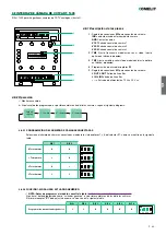
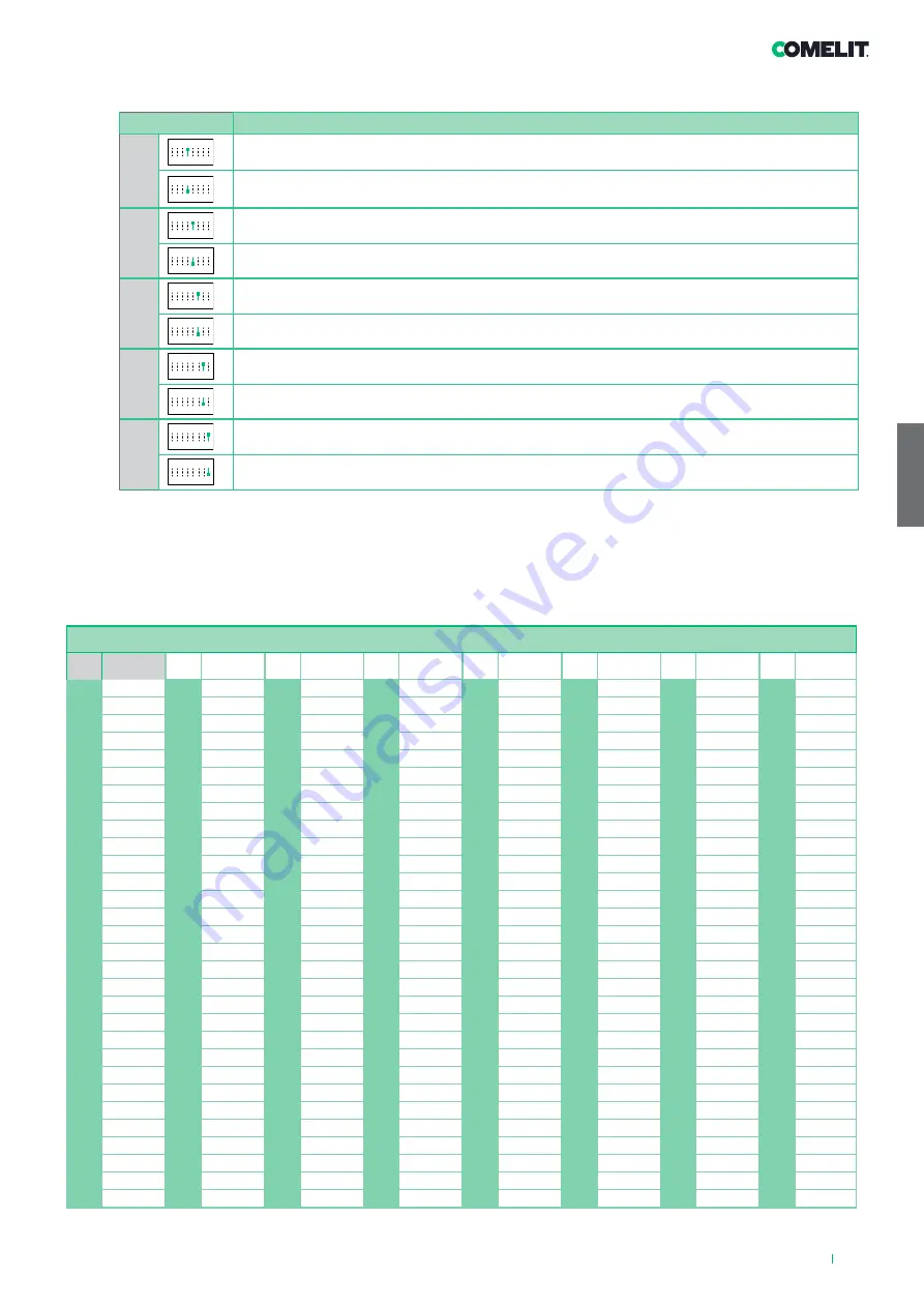
4.6.3 Código de usuario

TABLA A

código

Interruptor 

DIP ON

1

1

31

1,2,3,4,5

61

1,3,4,5,6

91

1,2,4,5,7

121

1,4,5,6,7

151

1,2,3,5,8

181

1,3,5,6,8

211

1,2,5,7,8

2

2

32

6

62

2,3,4,5,6

92

3,4,5,7

122

2,4,5,6,7

152

4,5,8

182

2,3,5,6,8

212

3,5,7,8

3

1,2

33

1,6

63

1,2,3,4,5,6

93

1,3,4,5,7

123

1,2,4,5,6,7

153

1,4,5,8

183

1,2,3,5,6,8

213

1,3,5,7,8

4

3

34

2,6

64

7

94

2,3,4,5,7

124

3,4,5,6,7

154

2,4,5,8

184

4,5,6,8

214

2,3,5,7,8

5

1,3

35

1,2,6

65

1,7

95

1,2,3,4,5,7

125

1,3,4,5,6,7

155

1,2,4,5,8

185

1,4,5,6,8

215

1,2,3,5,7,8

6

2,3

36

3,6

66

2,7

96

6,7

126

2,3,4,5,6,7

156

3,4,5,8

186

2,4,5,6,8

216

4,5,7,8

7

1,2,3

37

1,3,6

67

1,2,7

97

1,6,7

127

1,2,3,4,5,6,7

157

1,3,4,5,8

187

1,2,4,5,6,8

217

1,4,5,7,8

8

4

38

2,3,6

68

3,7

98

2,6,7

128

8

158

2,3,4,5,8

188

3,4,5,6,8

218

2,4,5,7,8

9

1,4

39

1,2,3,6

69

1,3,7

99

1,2,6,7

129

1,8

159

1,2,3,4,5,8

189

1,3,4,5,6,8

219

1,2,4,5,7,8

10

2,4

40

4,6

70

2,3,7

100

3,6,7

130

2,8

160

6,8

190

2,3,4,5,6,8

220

3,4,5,7,8

11

1,2,4

41

1,4,6

71

1,2,3,7

101

1,3,6,7

131

1,2,8

161

1,6,8

191

1,2,3,4,5,6,8

221

1,3,4,5,7,8

12

3,4

42

2,4,6

72

4,7

102

2,3,6,7

132

3,8

162

2,6,8

192

7,8

222

2,3,4,5,7,8

13

1,3,4

43

1,2,4,6

73

1,4,7

103

1,2,3,6,7

133

1,3,8

163

1,2,6,8

193

1,7,8

223

1,2,3,4,5,7,8

14

2,3,4

44

3,4,6

74

2,4,7

104

4,6,7

134

2,3,8

164

3,6,8

194

2,7,8

224

6,7,8

15

1,2,3,4

45

1,3,4,6

75

1,2,4,7

105

1,4,6,7

135

1,2,3,8

165

1,3,6,8

195

1,2,7,8

225

1,6,7,8

16

5

46

2,3,4,6

76

3,4,7

106

2,4,6,7

136

4,8

166

2,3,6,8

196

3,7,8

226

2,6,7,8

17

1,5

47

1,2,3,4,6

77

1,3,4,7

107

1,2,4,6,7

137

1,4,8

167

1,2,3,6,8

197

1,3,7,8

227

1,2,6,7,8

18

2,5

48

5,6

78

2,3,4,7

108

3,4,6,7

138

2,4,8

168

4,6,8

198

2,3,7,8

228

3,6,7,8

19

1,2,5

49

1,5,6

79

1,2,3,4,7

109

1,3,4,6,7

139

1,2,4,8

169

1,4,6,8

199

1,2,3,7,8

229

1,3,6,7,8

20

3,5

50

2,5,6

80

5,7

110

2,3,4,6,7

140

3,4,8

170

2,4,6,8

200

4,7,8

230

2,3,6,7,8

21

1,3,5

51

1,2,5,6

81

1,5,7

111

1,2,3,4,6,7

141

1,3,4,8

171

1,2,4,6,8

201

1,4,7,8

231

1,2,3,6,7,8

22

2,3,5

52

3,5,6

82

2,5,7

112

5,67

142

2,3,4,8

172

3,4,6,8

202

2,4,7,8

232

4,6,7,8

23

1,2,3,5

53

1,3,5,6

83

1,2,5,7

113

1,5,6,7

143

1,2,3,4,8

173

1,3,4,6,8

203

1,2,4,7,8

233

1,4,6,7,8

24

4,5

54

2,3,5,6

84

3,5,7

114

2,5,6,7

144

5,8

174

2,3,4,6,8

204

3,4,7,8

234

2,4,6,7,8

25

1,4,5

55

1,2,3,5,6

85

1,3,5,7

115

1,2,5,6,7

145

1,5,8

175

1,2,3,4,6,8

205

1,3,4,7,8

235

1,2,4,6,7,8

26

2,4,5

56

4,5,6

86

2,3,5,7

116

3,5,6,7

146

2,5,8

176

5,6,8

206

2,3,4,7,8

236

3,4,6,7,8

27

1,2,4,5

57

1,4,5,6

87

1,2,3,5,7

117

1,3,5,6,7

147

1,2,5,8

177

1,5,6,8

207

1,2,3,4,7,8

237

1,3,4,6,7,8

28

3,4,5

58

2,4,5,6

88

4,5,7

118

2,3,5,6,7

148

3,5,8

178

2,5,6,8

208

5,7,8

238

2,3,4,6,7,8

29

1,3,4,5

59

1,2,4,5,6

89

1,4,5,7

119

1,2,3,5,6,7

149

1,3,5,8

179

1,2,5,6,8

209

1,5,7,8

239

1,2,3,4,6,7,8

30

2,3,4,5

60

3,4,5,6

90

2,4,5,7

120

4,5,6,7

150

2,3,5,8

180

3,5,6,8

210

2,5,7,8

240

5,6,7,8

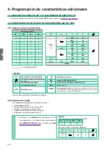
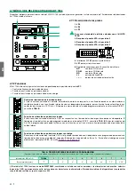
4.6.2 Programación de funciones


„

Ajuste los interruptores DIP 

S1

 correspondientes a la función que desee programar como se muestra en la siguiente tabla

DIP S1

FUNCIÓN

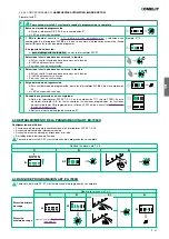
DIP 4

ON

1 2 3 4 6 7

5

8

El relé del abrepuertas y el segundo relé se controlan mediante 2 botones independientes (por ejemplo, botón 

del abrepuertas y botón del actuador) 

ON

1 2 3 4 6 7

5

8

 *

El relé del abrepuertas y el segundo relé se controlan mediante un único botón (por ejemplo, botón del 

abrepuertas) 

DIP 5

ON

1 2 3 4 6 7

5

8

Tiempo de activación del abrepuertas y tiempo de activación del relé: 8 s

ON

1 2 3 4 6 7

5

8

 *

tiempo de activación del abrepuertas y tiempo de activación del relé: 2 s

DIP 6

ON

1 2 3 4 6 7

5

8

Tonos de confirmación (llamada, abrepuertas, relé, audio activado): desactivados

ON

1 2 3 4 6 7

5

8

 *

Tonos de confirmación (llamada, abrepuertas, relé, audio activado): activados 

DIP 7

ON

1 2 3 4 6 7

5

8

LED de iluminación de la cámara: desactivado

ON

1 2 3 4 6 7

5

8

 *

LED de iluminación de la cámara: activado 

DIP 8

ON

1 2 3 4 6 7

5

8

Tiempo de espera de restablecimiento: 1 seg.

ON

1 2 3 4 6 7

5

8

 *

Tiempo de espera de restablecimiento: 10 seg.

* Valor predeterminado

Summary of Contents for HFX-700B

Page 1: ...MANUAL TÉCNICO MYCOMELIT THE APP FOR PROFESSIONALS MYCOMELIT L APPLI POUR LES PROFESSIONNELS MYCOMELIT LA APP DEL PROFESIONAL Complete technical manual for Single User Kit HFX 700B Manuel technique complet pour le Kit à un usager HFX 700B Manual técnico integral del Kit de Usuario Único HFX 700B ...

Page 2: ... your home or office Visitors activate the system by pressing a call pad on the external unit which sounds a doorbell chime as well as turning on the inside hands free video monitor A two way intercom then lets you speak with visitors after first visually identifying them It consists of a hands free monitor station and an external unit This kit is capable of expanding up to a total of 4 indoor mon...

Page 3: ...OR MODE 23 4 3 RESET PROGRAMMING ART EX 7000H 23 4 4 RANGE PROGRAMMING ART EX 7000H 23 4 5 DOOR ENTRY MONITOR RINGTONE SELECTION ART EX 7000H 24 4 6 CONFIGURATION EX B 24 4 6 1 External unit addressing 24 4 6 2 Function programming 25 4 6 3 User code 25 4 7 ACTUATOR RELAY MODULE ART 1256 26 4 7 1 Parts description 26 4 7 2 Functions 26 4 8 CCTV CAMERA INTERFACE ART 1409 27 4 8 1 Parts description ...

Page 4: ...X 7000H 1209 4 EX B HFX 700B Kit EX B External unit screws power supply 1 2 1209 4 BUS Power supply Technical manual Nameplate for 1 user screws external unit 2 2 dry wall anchors 1 YOUR NAME external unit door entry monitor power supply backplate Nameplate dry wall anchors dry wall anchors screws screws screws for 1 user ...

Page 5: ...mally open contact C relay common contact 3 Microphone 4 Wide angle colour camera 5 Camera lighting LED It can be disabled by setting DIP 7 to ON see page 25 4 6 2 Function programming 6 Nameplate 7 Call button 8 Adjustment trimmer See page 18 9 Addressing and programming DIP switches 10 CNF Programming confirmation button 11 S2 Special programming selector 12 S1 Button programming selector 13 Lou...

Page 6: ...for programming keys and functions DIP 1 2 3 4 for key function programming DIP 5 6 access to programming DIP 7 unused DIP 8 leave default setting OFF 10 Factory setting DO NOT CHANGE 11 Factory setting DO NOT CHANGE 12 CV 5 Video closing jumper 13 Pin for securing terminal block Terminal block for system connection L L Bus line connection terminals CFP1 CFP2 Outside door call input 2 2 EX 7000H D...

Page 7: ...s the key again to cycle through several external unit 1 2 key programmable INTERCOM FUNCTION Internal intercom function can be used to make a call to the internal units with the same user code General intercom to another user code can be used to make a call to the internal units with another user code 1 2 key programmable AUTOMATIC LOCK RELASE DOCTOR MODE Can be used to enable automatic activatio...

Page 8: ... main external unit connection 1 LP LP external unit connection 2 L1 L1 door entry monitor connection 1 L2 L2 door entry monitor connection 2 L3 L3 door entry monitor connection 3 L4 L4 door entry monitor connection 4 3 Video closing jumpers REMOVE WHEN LINE IS USED 4 L N mains power input 110 240 V 4 17 in 3 52 in 2 44 in 50 60Hz OUTPUT SORTIE 34V 0 5A 2A 1 on 5 off ta 40 C 110V 240V 1 4A L N L4 ...

Page 9: ...output 3 System installation Wire Assignment Wire Assignment Wire Type A max B max C max SINGLE PAIR CABLE CAT5 24AWG 1 115 feet 340 m 557 feet 170 m 557 feet 170 m DOUBLE PAIR CABLE CAT5 24AWG 1 312 feet 400 m 656 feet 200 m 656 feet 200 m MULTI PAIR CABLE FOLLOW THE COLORS SHOWN IN THE DIAGRAM GREEN ORANGE BLU GREEN WHITE ORANGE WHITE BLU WHITE BROWN WHITE BROWN CAT5 24AWG 1 312 feet 400 m 656 f...

Page 10: ...nsion external unit expansion door entry monitor expansion door entry monitor NOTE This system is capable to expanding up to 4 external units and 4 internal units For alternative application please consult our technical support engineer first At the first connection on the riser the internal units automatically acquire theirs sub addresses The LEDs and flash simultaneously for some seconds After t...

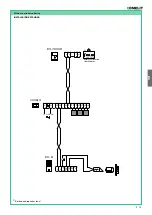
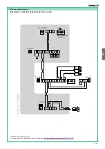
Page 11: ...EX 7000H 1209 4 L1 L1 L2 L2 L N 110 240V LP LP L3 L3 L4 L4 S1 A LEAVE DEFAULT SETTING ON 1 2 3 4 6 7 5 8 L L E T R NO GND SE SE C EX B Local lock release button LEAVE DEFAULT SETTINGS STANDARD INSTALLATION Basic single user kit ...

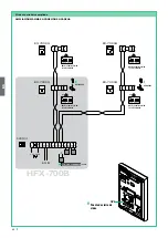
Page 12: ... LINE IS USED REMOVE CV5 HFX 700B REMOVE CV5 S1 A LEAVE DEFAULT SETTING ON 1 2 3 4 6 7 5 8 S1 A LEAVE DEFAULT SETTING ON 1 2 3 4 6 7 5 8 S1 A LEAVE DEFAULT SETTING ON 1 2 3 4 6 7 5 8 S1 A LEAVE DEFAULT SETTING ON 1 2 3 4 6 7 5 8 LEAVE DEFAULT SETTINGS LEAVE DEFAULT SETTINGS LEAVE DEFAULT SETTINGS LEAVE DEFAULT SETTINGS REMOVE WHEN LINE IS USED REMOVE CV5 REMOVE CV5 MAXIMUM EXPANSION IN DAISY CHAIN...

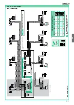
Page 13: ...E DEFAULT SETTING ON 1 2 3 4 6 7 5 8 ON 1 2 3 4 6 7 5 8 ON 1 2 3 4 6 7 5 8 ON 1 2 3 4 6 7 5 8 L L E T R NO GND SE SE C EX B L L E T R NO GND SE SE C EX B L L E T R NO GND SE SE C EX B L L E T R NO GND SE SE C EX B LEAVE DEFAULT SETTINGS LEAVE DEFAULT SETTINGS LEAVE DEFAULT SETTINGS LEAVE DEFAULT SETTINGS LEAVE DEFAULT SETTINGS SET THE ADDRESS SET THE ADDRESS SET THE ADDRESS REMOVE WHEN LINE IS USE...

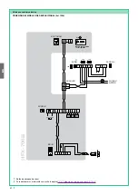
Page 14: ...L C F P 1 2 1209 4 L1 L1 L2 L2 L N 110 240V LP LP L3 L3 L4 L4 S1 A LEAVE DEFAULT SETTING ON 1 2 3 4 6 7 5 8 L L E T R NO GND SE SE C EX B EX 7000H LEAVE DEFAULT SETTINGS For further information see page 26 4 7 Actuator relay module Art 1256 Local lock release button Basic single user kit ADDITIONAL RELAY MODULE Art 1256 CONNECTION ...

Page 15: ...09 4 L1 L1 L2 L2 L N 110 240V LP LP L3 L3 L4 L4 S1 A LEAVE DEFAULT SETTING ON 1 2 3 4 6 7 5 8 ON 1 2 3 4 6 7 5 8 L L E T R NO GND SE SE C EX B LEAVE DEFAULT SETTINGS Local lock release button For further information see page 27 4 8 CCTV camera interface ART 1409 Basic single user kit CCTV CAMERA INTERFACE Art 1409 CONNECTION ...

Page 16: ...3 1 2 REMOVING THE TERMINAL L L C F P 1 C F P 2 1 2 3 INSERTING THE TERMINAL 4 3 2 2 3 1 TO OPEN 1 2 3 5 63 in 51 18 in optional fixing 1 optional fixing 3 2 ASSEMBLY MINI HANDSFREE ART EX 7000H INTERNAL UNIT ...

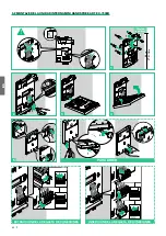
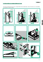
Page 17: ... 28 in 81 10 in 79 19 68 in 19 68 in 19 68 in 32 28 in 67 32 in 51 18 in 79 59 05 in 32 28 in 75 19 in 79 43 70 in 96 19 68 in 64 96 in 32 28 in 81 10 in 79 19 68 in 19 68 in 19 68 in 32 28 in 67 32 in 51 18 in 79 59 05 in 32 28 in 75 19 in 79 43 70 in 96 19 68 in 19 68 in 32 28 in 67 32 in 51 18 in 79 43 70 in 96 19 68 in 64 96 in 32 28 in 81 10 in 79 19 68 in 19 68 in 19 68 in 32 28 in 67 32 in ...

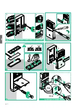
Page 18: ...EN 18 ADJUST IF NEEDED DO NOT CHANGE Microphone DO NOT CHANGE Loudspeaker JOHNDOE 1 2 JOHNDOE J O H N D O E 7 8 9 6 REMOVE TERMINAL IF NEEDED 1 2 3 5B ...

Page 19: ...EN 19 3 3 1 How to change the nameplate of the external unit art EX B FAM SMITH 1 2 F A M S M I T H 5 6 CLACK JOHNDOE JOHNDOE 1 3 4 JOHNDOE 2 ...

Page 20: ...N D AUTOMATIC LOCK RELASE DOCTOR MODE LOCK RELEASE FUNCTION NULL No function ACT ACTUATOR FUNCTION PROG Programmed functions in this DIP switch setting the buttons control the programmed functions the NON programmed buttons control functions referred to on line 0000 See description functions on page 7 4 2 2 Quick programming For the quick programming of the following functions generic actuator ACT...

Page 21: ...t programming mode To exit programming mode set S2 DIP switches 5 6 to the combination 00 the Privacy LED switches off ON 1 2 3 4 6 7 5 8 5 When programming is complete Set S2 DIP switches 1 2 3 4 to the combination 1111 PROG setting In this DIP switch setting the keys control the programmed functions the NON programmed keys control functions referred to on line 0000 see Preset function table Rest...

Page 22: ...witches off ON 1 2 3 4 6 7 5 8 5 When programming is complete Set S2 DIP switches 1 2 3 4 to the combination 1111 PROG setting In this DIP switch setting the keys control the programmed functions the NON programmed keys control functions referred to on line 0000 see Preset function table Restore the user code setting on S1 ON 1 2 3 4 6 7 5 8 ON 1 2 3 4 6 7 5 8 4 2 3 4 HOW TO PROGRAM THE SELF ACTIV...

Page 23: ...programming mode To exit programming mode set S2 DIP switches 5 6 to the combination 00 the Privacy LED switches off ON 1 2 3 4 6 7 5 8 5 When programming is complete Set S2 DIP switches 1 2 3 4 to the combination 1111 PROG setting In this DIP switch setting the keys control the programmed functions the NON programmed keys control functions referred to on line 0000 see Preset function table Restor...

Page 24: ...nes are emitted to change the ringtone for intercom calls made from the internal unit 4 times 4 confirmation tones are emitted to change the floor door call ringtone Any further pressing of the key repeats the sequence described above 3 Press and release to scroll through the various available ringtones in sequence 4 Press to confirm selection of the last ringtone heard and to exit at any time cha...

Page 25: ... 3 4 8 170 2 4 6 8 200 4 7 8 230 2 3 6 7 8 21 1 3 5 51 1 2 5 6 81 1 5 7 111 1 2 3 4 6 7 141 1 3 4 8 171 1 2 4 6 8 201 1 4 7 8 231 1 2 3 6 7 8 22 2 3 5 52 3 5 6 82 2 5 7 112 5 67 142 2 3 4 8 172 3 4 6 8 202 2 4 7 8 232 4 6 7 8 23 1 2 3 5 53 1 3 5 6 83 1 2 5 7 113 1 5 6 7 143 1 2 3 4 8 173 1 3 4 6 8 203 1 2 4 7 8 233 1 4 6 7 8 24 4 5 54 2 3 5 6 84 3 5 7 114 2 5 6 7 144 5 8 174 2 3 4 6 8 204 3 4 7 8 ...

Page 26: ...osure time can be programmed using a S1 DIP switch see TAB B JP1 JP1 JP1 JP1 JP1 JP1 JP2 1 2 JP4 1 2 JP3 1 2 Activation function on Actuator pushbutton The relay is operated by closing the C NO contact in response to a Generic actuator call from a video entry phone The relay closure time can be programmed using a S1 DIP switch see TAB B All Art 1256 modules set for use with this function are activ...

Page 27: ...generic actuator it is possible to toggle between the different cameras Microswitch S1 must be set as shown in following table DIP 1 DIP 2 DIP 3 DIP 4 DIP 5 DIP 6 Setting for generic actuator 1 1 0 0 0 0 ON 1 2 3 4 6 7 5 8 4 8 CCTV CAMERA INTERFACE ART 1409 Art 1409 allows to manage analog CCTV camera up to 3 4 8 1 Parts description 1 Terminal block M2 for system connection INA camera module exter...

Page 28: ...2 DIP 3 DIP 4 DIP 5 DIP 6 Example of Address setting on art 1409 for control using actuator code 224 1 0 0 0 1 0 ON 1 2 3 4 6 7 5 8 In this mode with the video entry phone monitor switched on by repeatedly pressing the actuator with code pushbutton it is possible to cycle through ONLY the cameras connected to module 1409 with the corresponding address In the same system it is possible to install u...

Page 29: ...he other internal units This function can be used to transmit a call to the other internal units set to the same user code or set to another user code for programming see page 20 4 2 Configuration Capacitive touch keys Art Ex 7000H Press the programmed button to send the call If the system is busy the LED will flash 4 times 5 1 4 How to answer a call from an internal unit On receipt of a call from...

Page 30: ...through several cameras If a call is underway with an external unit it is NOT possible to cycle between the external units 5 4 1 How to display on the door entry monitor the image transmitted from the CCTV camera During call in progress or during Self activation Press the programmed button to display on the monitor the image transmitted from the CCTV camera Press again to cycle through several cam...

Page 31: ...TOMATIC LOCK RELASE DOCTOR MODE D set to 3 Sec Press the programmed button for 3 sec to disable enable the Automatic lock relase 3 flashes every 5 sec of the LED indicate that the Automatic lock relase is active 5 7 ACTIVATION DEACTIVATION AUTOMATIC ANSWER MODE 10 Sec Press for 10 sec to activate deactivate automatic answer mode A confirmation tone will sound The LED indicates that the automatic a...

Page 32: ...EN 32 5 8 BRIGHTNESS CONTROL 5 9 LOUDSPEAKER VOLUME CONTROL To increase the brightness turn clockwise To increase the volume turn clockwise ...

Page 33: ...00mA for 12VAC DC locks maximum impedance 18 Ohm Door release relay contact C NO 10A 12 24 VAC VDC Loudspeaker volume control Yes Microphone volume control Yes IP protection rating IP54 Operating temperature 13 F 131 F 25 C 55 C Operating humidity RH max 0 95 Environmental class IV for use out of doors where the system components are fully exposed to the weather 6 3 BUS POWER SUPPLY ART 1209 4 Pow...

Page 34: ...quiring Service The unit should be serviced by a qualified service personnel when The power supply cord or the plug has been damaged or Objects have fallen or liquid has been spilled onto the equipment or The equipment has been exposed to rain or The equipment does not appear to operate normally or exhibits a marked change in performance or The equipment has been dropped and or the enclosure has b...

Page 35: ...ENERAL PRODUCT WARRANTY For all Comelit Branded Products 2 year manufacturer s warranty from dealer date of Purchase Proof of purchase by the dealer in the form of an invoice is necessary for all returns RMA RETURN Policy 1 Before Requesting an RMA Number the installer must call into our Tech support line to verify the condition of the product and for trouble shooting purposes in order for Comelit...

Page 36: ...re domicile ou de votre bureau Les visiteurs activent le système en appuyant sur un bouton d appel du poste extérieur Une sonnerie retentit alors et le moniteur vidéo mains libres à l intérieur s allume Un système intercom à deux voies vous permet alors de parler avec les visiteurs après les avoir identifiés visuellement Il est constitué d un poste moniteur mains libres et d un poste extérieur Ce ...

Page 37: ...ROGRAMMATION DE L ART EX 7000H 57 4 4 PROGRAMMATION DE LA PLAGE ART EX 7000H 57 4 5 SÉLECTION DE LA LA SONNERIE DU VISIOPHONE ART EX 7000H 58 4 6 CONFIGURATION EX B 58 4 6 1 Adressage du poste extérieur 58 4 6 2 Fonction programmation 59 4 6 3 Code d accès 59 4 7 MODULE DU RELAIS DE L ACTIONNEUR ART 1256 60 4 7 1 Description des pièces 60 4 7 2 Fonctions 60 4 8 INTERFACE CAMÉRA CCTV ART 1409 61 4 ...

Page 38: ...0B EX B Poste extérieur screws power supply 1 2 Alimentation électrique BUS 1209 4 Manuel Technique Nameplate for 1 user screws external unit 2 2 dry wall anchors 1 YOUR NAME poste extérieur Visiophone alimentation électrique étrier Plaque signalétique ancrages pour cloisons sèches ancrages pour cloisons sèches vis vis vis pour 1 usager ...

Page 39: ...is normalement ouvert C contact relais commun 3 Micro 4 Caméra grand angle couleur 5 Éclairage LED caméra Il peut être désactivé en réglant le DIP 7 sur ON voir page 59 4 6 2 Fonction programmation 6 Plaque signalétique 7 Bouton Appel 8 Trimmer de réglage Voir page 52 9 Adressage et programmation des DIP switches 10 CNF bouton de confirmation de la programmation 11 S2 Sélecteur de programmation sp...

Page 40: ...rammation des touches et des fonctions DIP 1 2 3 4 pour la programmation des fonctions des touches DIP 5 6 accès à la programmation DIP 7 non utilisé DIP 8 garder le réglage par défaut OFF 10 Réglage du fabricant NE PAS MODIFIER 11 Réglage du fabricant NE PAS MODIFIER 12 CV 5 Cavalier de fermeture vidéo 13 Broche de verrouillage du bornier Bornier pour la connexion de l installation L L Bornes de ...

Page 41: ...is sur la touche pour passer d un poste extérieur à l autre Touche 1 2 programmable FONCTION INTERCOMMUNICATION Fonction intercommunicante interne peut être utilisée pour effectuer un appel vers les postes intérieurs avec le même code d accès Intercommunication générique vers un autre code d accès peut être utilisée pour effectuer un appel vers les postes intérieurs avec un autre code d accès Touc...

Page 42: ...dementposteextérieursupplémentaire LP LP raccordement poste extérieur principal 1 LP LP raccordement poste extérieur 2 L1 L1 raccordement 1 visiophone L2 L2 raccordement 2 visiophone L3 L3 raccordement 3 visiophone L4 L4 raccordement 4 visiophone 3 Cavaliers de fermeture vidéo SUPPRIMER LORSQUE LA LIGNE EST UTILISÉE 4 L N entrée alimentation réseau 110 240 V 4 17 in 3 52 in 2 44 in 50 60Hz OUTPUT ...

Page 43: ...ibution du câble Attribution du câble Type de câble A max B max C max CÂBLE PAIRE SIMPLE CAT5 24AWG 1 115 pieds 340 m 557 pieds 170 m 557 pieds 170 m CÂBLE PAIRE DOUBLE CAT5 24AWG 1 312 pieds 400 m 656 pieds 200 m 656 pieds 200 m CÂBLE PAIRES MULTIPLES RESPECTER LES COULEURS INDIQUÉES SUR LE SCHÉMA GREEN ORANGE BLU GREEN WHITE ORANGE WHITE BLU WHITE BROWN WHITE BROWN CAT5 24AWG 1 312 pieds 400 m 6...

Page 44: ...ension visiophone extension visiophone REMARQUE Ce système peut contenir jusqu à 4 postes extérieurs et 4 postes intérieurs Pour d autres applications veuillez consulter notre assistance technique au préalable Lorsque la colonne montante est raccordée pour la première fois les postes intérieurs acquièrent automatiquement leur sous adresse Les LED et clignotent simultanément pendant quelques second...

Page 45: ...0H 1209 4 L1 L1 L2 L2 L N 110 240V LP LP L3 L3 L4 L4 S1 A LEAVE DEFAULT SETTING ON 1 2 3 4 6 7 5 8 L L E T R NO GND SE SE C EX B Bouton ouvre porte local LAISSER LES PARAMÈTRES PAR DÉFAUT INSTALLATION STANDARD Kit de base à un usager ...

Page 46: ...E CV5 S1 A LEAVE DEFAULT SETTING ON 1 2 3 4 6 7 5 8 S1 A LEAVE DEFAULT SETTING ON 1 2 3 4 6 7 5 8 S1 A LEAVE DEFAULT SETTING ON 1 2 3 4 6 7 5 8 S1 A LEAVE DEFAULT SETTING ON 1 2 3 4 6 7 5 8 LAISSER LES PARAMÈTRES PAR DÉFAUT LAISSER LES PARAMÈTRES PAR DÉFAUT LAISSER LES PARAMÈTRES PAR DÉFAUT LAISSER LES PARAMÈTRES PAR DÉFAUT SUPPRIMER LORSQUE LA LIGNE EST UTILISÉE SUPPRIMER CV5 SUPPRIMER CV5 ÉVOLUT...

Page 47: ...5 8 ON 1 2 3 4 6 7 5 8 ON 1 2 3 4 6 7 5 8 L L E T R NO GND SE SE C EX B L L E T R NO GND SE SE C EX B L L E T R NO GND SE SE C EX B L L E T R NO GND SE SE C EX B LAISSERLES PARAMÈTRES PAR DÉFAUT LAISSERLES PARAMÈTRES PAR DÉFAUT LAISSERLES PARAMÈTRES PAR DÉFAUT LAISSERLES PARAMÈTRES PAR DÉFAUT LAISSERLES PARAMÈTRES PAR DÉFAUT DÉFINIR L ADRESSE DÉFINIR L ADRESSE DÉFINIR L ADRESSE SUPPRIMER LORSQUE L...

Page 48: ...1209 4 L1 L1 L2 L2 L N 110 240V LP LP L3 L3 L4 L4 S1 A LEAVE DEFAULT SETTING ON 1 2 3 4 6 7 5 8 L L E T R NO GND SE SE C EX B EX 7000H LAISSER LES PARAMÈTRES PAR DÉFAUT Pour plus d informations voir la page 60 4 7 Module du relais de l actionneur art 1256 Bouton ouvre porte local Kit de base à un usager MODULE DE RELAIS SUPPLÉMENTAIRE art 1256 ...

Page 49: ...L2 L2 L N 110 240V LP LP L3 L3 L4 L4 S1 A LEAVE DEFAULT SETTING ON 1 2 3 4 6 7 5 8 ON 1 2 3 4 6 7 5 8 L L E T R NO GND SE SE C EX B LAISSER LES PARAMÈTRES PAR DÉFAUT Bouton ouvre porte local Pour plus d informations voir la page 61 4 8 Interface caméra CCTV ART 1409 Kit de base à un usager BRANCHEMENT DE L INTERFACE CAMÉRA CCTV art 1409 ...

Page 50: ... DÉMONTAGE DU BORNIER L L C F P 1 C F P 2 1 2 3 MONTAGE DU BORNIER 4 3 2 2 3 1 POUR OUVRIR 1 2 3 5 63 in 51 18 in optional fixing 1 fixation optionnelle 3 2 ENSEMBLE MINI MAINS LIBRES ART EX 7000H POSTE INTÉRIEUR ...

Page 51: ...K 2 1 5A 3 4 64 96 in 32 28 in 81 10 in 79 19 68 in 19 68 in 19 68 in 32 28 in 67 32 in 51 18 in 79 59 05 in 32 28 in 75 19 in 79 43 70 in 96 19 68 in 64 96 in 32 28 in 81 10 in 79 19 68 in 19 68 in 19 68 in 32 28 in 67 32 in 51 18 in 79 59 05 in 32 28 in 75 19 in 79 43 70 in 96 19 68 in 19 68 in 32 28 in 67 32 in 51 18 in 79 43 70 in 96 19 68 in 64 96 in 32 28 in 81 10 in 79 19 68 in 19 68 in 19 ...

Page 52: ...FR 52 RÉGLER SI NÉCESSAIRE DO NOT CHANGE Micro NE PAS CHANGER Haut parleur JOHNDOE 1 2 JOHNDOE J O H N D O E 7 8 9 6 ENLEVER LE TERMINAL SI NÉCESSAIRE 1 2 3 5B ...

Page 53: ...FR 53 3 3 1 Remplacement de l étiquette porte noms du poste extérieur art EX B FAM SMITH 1 2 F A M S M I T H 5 6 CLACK JOHNDOE JOHNDOE 1 3 4 JOHNDOE 2 ...

Page 54: ... MÉDECIN FONCTION DÉVERROUILLAGE NUL Aucune fonction ACT FONCTION actionneur PROG Fonctions programmées dans ce réglage du DIP switch les boutons commandent les fonctions programmées les boutons NON programmés commandent les fonctions indiquées à la ligne 0000 Voir la description des fonctions à la page 7 4 2 2 Programmation rapide Pour la programmation rapide des fonctions suivantes actionneur gé...

Page 55: ... 4 Quitter le mode programmation Pour quitter le mode programmation régler les DIP switches S2 5 6 sur la combinaison 00 la LED Privacy s éteint ON 1 2 3 4 6 7 5 8 5 Au terme de la programmation Régler les DIP switches S2 1 2 3 4 sur la combinaison 1111 réglage PROG Dans ce réglage de dip switch les touches commandent les fonctions programmées les touches NON programmées commandent les fonctions i...

Page 56: ...s éteint ON 1 2 3 4 6 7 5 8 5 Au terme de la programmation Régler les DIP switches S2 1 2 3 4 sur la combinaison 1111 réglage PROG Dans ce réglage de DIP switch les touches commandent les fonctions programmées les touches NON programmées commandent les fonctions indiquées à la ligne 0000 voir 4 2 1 Tableau fonction de présélection Rétablir le réglage du code d accès sur S1 ON 1 2 3 4 6 7 5 8 ON 1 ...

Page 57: ...r le mode programmation régler les DIP switches S2 5 6 sur la combinaison 00 la LED Privacy s éteint ON 1 2 3 4 6 7 5 8 5 Au terme de la programmation Régler les DIP switches S2 1 2 3 4 sur la combinaison 1111 réglage PROG Dans ce réglage de DIP switch les touches commandent les fonctions programmées les touches NON programmées commandent les fonctions indiquées à la ligne 0000 voir 4 2 1 Tableau ...

Page 58: ...fier la sonnerie des appels intercommunicants effectués depuis le poste intérieur 4 fois émission de 4 tonalités de confirmation pour modifier la sonnerie de l appel palier En appuyant une nouvelle fois sur la touche la séquence indiquée ci dessus reprend depuis le départ 3 Appuyer et relâcher pour faire défiler les différentes sonneries disponibles en séquence 4 Appuyer sur pour confirmer la séle...

Page 59: ... 3 5 51 1 2 5 6 81 1 5 7 111 1 2 3 4 6 7 141 1 3 4 8 171 1 2 4 6 8 201 1 4 7 8 231 1 2 3 6 7 8 22 2 3 5 52 3 5 6 82 2 5 7 112 5 67 142 2 3 4 8 172 3 4 6 8 202 2 4 7 8 232 4 6 7 8 23 1 2 3 5 53 1 3 5 6 83 1 2 5 7 113 1 5 6 7 143 1 2 3 4 8 173 1 3 4 6 8 203 1 2 4 7 8 233 1 4 6 7 8 24 4 5 54 2 3 5 6 84 3 5 7 114 2 5 6 7 144 5 8 174 2 3 4 6 8 204 3 4 7 8 234 2 4 6 7 8 25 1 4 5 55 1 2 3 5 6 85 1 3 5 7 ...

Page 60: ...re du relais peut être programmé à l aide d un DIP switch S1 voir le TABLEAU B JP1 JP1 JP1 JP1 JP1 JP1 JP2 1 2 JP4 1 2 JP3 1 2 Fonction activation sur le bouton poussoir de l actionneur Le relais est activé en fermant le contact C NO en réponse à un appel de l actionneur générique depuis une installation vidéophonique Le temps de fermeture du relais peut être programmé à l aide d un DIP switch S1 ...

Page 61: ...er d une caméra à l autre Le microswitch S1 doit être réglé comme indiqué dans le tableau suivant DIP 1 DIP 2 DIP 3 DIP 4 DIP 5 DIP 6 Programmation pour l actionneur générique 1 1 0 0 0 0 ON 1 2 3 4 6 7 5 8 4 8 INTERFACE CAMÉRA CCTV ART 1409 L art 1409 permet de gérer la caméra CCTV analogique jusqu à 3 4 8 1 Description des pièces 1 Boîte à bornes M2 pour connexion à l installation INA contact co...

Page 62: ...6 Exemple de réglage d adresse sur l art 1409 pour la commande utilisant le code d actionneur 224 1 0 0 0 1 0 ON 1 2 3 4 6 7 5 8 Avec ce mode à moniteur d appel vidéophonique allumé appuyer plusieurs fois sur l actionneur à l aide du bouton poussoir à code pour passer UNIQUEMENT entre les caméras qui sont connectées au module 1409 avec leur adresse correspondante Dans le même système il est possib...

Page 63: ...ieurs Cette fonction peut être utilisée pour transmettre un appel à d autres postes intérieurs réglés sur le même code d accès ou réglés sur un autre code d accès pour la programmation voir la page 54 4 2 Configuration des touches capacitives art Ex 7000H Appuyer sur le bouton programmé pour envoyer l appel Si le système est occupé la LED clignote 4 fois 5 1 4 Comment répondre à un appel d un post...

Page 64: ...te extérieur Appuyer à nouveau pour faire défiler les différentes caméras Il n est PAS possible de faire défiler les postes extérieurs si un appel est en cours avec le poste extérieur 5 4 1 Comment afficher sur le visiophone l image transmise par la caméra CCTV Durant un appel en cours ou l auto activation Appuyer sur le bouton programmé pour afficher à l écran l image transmise par la caméra CCTV...

Page 65: ...UTOMATIQUE MODE MÉDECIN D set to 3 Sec Appuyer 3 secondes sur le bouton programmé pour désactiver activer le déverrouillage automatique 3 clignotements toutes les 5 secondes de la LED indiquent que le déverrouillage automatique est activé 5 7 ACTIVATION DÉSACTIVATION DU MODE RÉPONSE AUTOMATIQUE 10 Sec Appuyer sur pendant 10 sec pour activer désactiver le mode réponse automatique Une sonnerie de co...

Page 66: ...RÉGLAGE DE LA LUMINOSITÉ 5 9 RÉGLAGE DU VOLUME DU HAUT PARLEUR Tourner dans le sens des aiguilles d une montre pour augmenter la luminosité Tourner dans le sens des aiguilles d une montre pour augmenter le volume ...

Page 67: ...rrures 12 VAC DC impédance maximale 18 Ohms Déverrouillage de la porte contact relais C NO 10 A 12 24 VAC VDC Contrôle du volume du haut parleur Oui Contrôle du volume du micro Oui Indice de protection IP IP54 Température de fonctionnement 13 F 131 F 25 C 55 C Humidité de service HR max 0 95 Classe environnementale IV pour une utilisation à l extérieur où les composants du système sont entièrement...

Page 68: ...mber d objets ou de liquides sur les éléments de l équipement Dommages nécessitant l intervention de l Assistance technique L unité doit être réparée par du personnel qualifié En cas de dommage du câble ou de la fiche d alimentation ou Lorsque des objets sont tombés ou lorsque des liquides se sont écoulés sur le dispositif ou En cas d exposition de l appareil à la pluie ou Lorsque l équipement sem...

Page 69: ...t sont couverts par 2 ans de garantie fabricant à partir de la date d achat concessionnaire Pour tous les retours un justificatif d achat de la part du distributeur sous forme de facture est nécessaire Politique RMA RETOUR 1 Avant de demander un numéro de RMA l installateur doit faire appel à notre service d assistance technique afin de vérifier l état du produit et les mesures de dépannage possib...

Page 70: ...sa u oficina Los visitantes activan el sistema pulsando una almohadilla de llamada de la unidad externa que hace sonar un timbre y activa el monitor de vídeo manos libres del interior A continuación un intercomunicador bidireccional permite hablar con los visitantes tras identificarlos primero visualmente Consta de una estación de monitor manos libres y una unidad externa Este kit permite ampliar ...

Page 71: ...ART EX 7000H 91 4 4 RANGO DE PROGRAMACIÓN ART EX 7000H 91 4 5 SELECCIÓN DEL TONO DE LLAMADA DEL VIDEOPORTERO ART EX 7000H 92 4 6 CONFIGURACIÓN EX B 92 4 6 1 Asignación de dirección a la unidad externa 92 4 6 2 Programación de funciones 93 4 6 3 Código de usuario 93 4 7 MÓDULO DE RELÉ DE ACTUADOR ART 1256 94 4 7 1 Descripción de las piezas 94 4 7 2 Funciones 94 4 8 INTERFAZ DE CÁMARA DE CCTV ART 14...

Page 72: ... Kit HFX 700B EX B Unidad externa screws power supply 1 2 1209 4 Alimentación del BUS Manual técnico Nameplate for 1 user screws external unit 2 2 dry wall anchors 1 YOUR NAME unidad externa videoportero alimentación placa soporte Portanombres anclajes de pared seca anclajes de pared seca tornillos tornillos tornillos para 1 usuario ...

Page 73: ...ontacto común de relé 3 Micrófono 4 Cámara en color de gran ángulo de visión 5 LED de iluminación de la cámara Se puede deshabilitar ajustando el DIP 7 en ON consulte la página 93 4 6 2 Programación de funciones 6 Portanombres 7 Botón de llamada 8 Ajuste trimmer Consulte la página 86 9 Asignación de dirección y programación de interruptores DIP 10 CNF Botón de confirmación de la programación 11 S2...

Page 74: ...amación de teclas y funciones DIP 1 2 3 4 para la programación de funciones de teclas DIP 5 6 acceso a la programación DIP 7 no se utiliza DIP 8 deje la configuración predeterminada OFF 10 Configuración de fábrica NO LA CAMBIE 11 Configuración de fábrica NO LA CAMBIE 12 CV 5 Puente de cierre de vídeo 13 Pasador para fijar la regleta de conexiones Regleta de conexiones para la conexión del sistema ...

Page 75: ...o para pasar por varias unidades externas Tecla 1 2 programable FUNCIÓN DE INTERCOMUNICACIÓN Función de intercomunicación interna se puede utilizar para realizar una llamada a las unidades internas con el mismo código de usuario Intercomunicación general con otro código de usuario se puede utilizar para realizar una llamada a las unidades internas con otro código de usuario Tecla 1 2 programable A...

Page 76: ...exión de la unidad externa adicional LP LP conexión de la unidad externa principal 1 LP LP conexión de unidad externa 2 L1 L1 conexión videoportero 1 L2 L2 conexión videoportero 2 L3 L3 conexión videoportero 3 L4 L4 conexión videoportero 4 3 Puentes de cierre de vídeo RETÍRELOS CUANDO SE UTILICE LA LÍNEA 4 L N entrada de alimentación de 110 240 V 4 17 in 3 52 in 2 44 in 50 60Hz OUTPUT SORTIE 34V 0...

Page 77: ...ema Asignación de cables Asignación de cables Tipo de cable A máx B máx C máx CABLE DE PAR SIMPLE CAT5 24AWG 1 115 pies 340 m 557 pies 170 m 557 pies 170 m CABLE DE PAR DOBLE CAT5 24AWG 1 312 pies 400 m 656 pies 200 m 656 pies 200 m CABLE DE PAR MÚLTIPLE SIGA LOS COLORES QUE SE MUESTRAN EN EL DIAGRAMA GREEN ORANGE BLU GREEN WHITE ORANGE WHITE BLU WHITE BROWN WHITE BROWN CAT5 24AWG 1 312 pies 400 m...

Page 78: ...terna de ampliación videoportero de expansión videoportero de expansión NOTA Este sistema puede ampliarse hasta 4 unidades externas y 4 unidades internas Para aplicaciones alternativas consulte primero con nuestro técnico de soporte En la primera conexión en la columna montante las unidades internas adquieren automáticamente sus subdirecciones Los ledes y parpadean simultáneamente durante algunos ...

Page 79: ...209 4 L1 L1 L2 L2 L N 110 240V LP LP L3 L3 L4 L4 S1 A LEAVE DEFAULT SETTING ON 1 2 3 4 6 7 5 8 L L E T R NO GND SE SE C EX B Botón de abrepuertas local DEJE LA CONFIGURACIÓN PREDETERMINADA INSTALACIÓN ESTÁNDAR Kit de usuario único básico ...

Page 80: ...0B REMOVE CV5 S1 A LEAVE DEFAULT SETTING ON 1 2 3 4 6 7 5 8 S1 A LEAVE DEFAULT SETTING ON 1 2 3 4 6 7 5 8 S1 A LEAVE DEFAULT SETTING ON 1 2 3 4 6 7 5 8 S1 A LEAVE DEFAULT SETTING ON 1 2 3 4 6 7 5 8 DEJE LA CONFIGURACIÓN PREDETERMINADA DEJE LA CONFIGURACIÓN PREDETERMINADA DEJE LA CONFIGURACIÓN PREDETERMINADA DEJE LA CONFIGURACIÓN PREDETERMINADA RETIRE CUANDO SE UTILICE LA LÍNEA RETIRE CV5 RETIRE CV...

Page 81: ...8 ON 1 2 3 4 6 7 5 8 L L E T R NO GND SE SE C EX B L L E T R NO GND SE SE C EX B L L E T R NO GND SE SE C EX B L L E T R NO GND SE SE C EX B DEJE LA CONFIGURACIÓN PREDETERMINADA DEJE LA CONFIGURACIÓN PREDETERMINADA DEJE LA CONFIGURACIÓN PREDETERMINADA DEJE LA CONFIGURACIÓN PREDETERMINADA DEJE LA CONFIGURACIÓN PREDETERMINADA CONFIGURE LA DIRECCIÓN CONFIGURE LA DIRECCIÓN CONFIGURE LA DIRECCIÓN RETIR...

Page 82: ...L1 L2 L2 L N 110 240V LP LP L3 L3 L4 L4 S1 A LEAVE DEFAULT SETTING ON 1 2 3 4 6 7 5 8 L L E T R NO GND SE SE C EX B EX 7000H DEJE LA CONFIGURACIÓN PREDETERMINADA Para obtener más información consulte la página 94 4 7 Módulo de relé de actuador Art 1256 Botón de abrepuertas local Kit de usuario único básico CONEXIÓN DEL MÓDULO DE RELÉ ADICIONAL Art 1256 ...

Page 83: ...240V LP LP L3 L3 L4 L4 S1 A LEAVE DEFAULT SETTING ON 1 2 3 4 6 7 5 8 ON 1 2 3 4 6 7 5 8 L L E T R NO GND SE SE C EX B DEJE LA CONFIGURACIÓN PREDETERMINADA Botón de abrepuertas local Para obtener más información consulte la página 95 4 8 Interfaz de cámara de CCTV ART 1409 Kit de usuario único básico CONEXIÓN DE LA INTERFAZ DE CÁMARA DE CCTV Art 1409 ...

Page 84: ... REGLETA DE CONEXIONES L L C F P 1 C F P 2 1 2 3 INSERCIÓN DE LA REGLETA DE CONEXIONES 4 3 2 2 3 1 PARA ABRIR 1 2 3 5 63 in 51 18 in optional fixing 1 fijación opcional 3 2 MONTAJE DE LA UNIDAD INTERNA MINI HANDSFREE ART EX 7000H ...

Page 85: ...28 in 81 10 in 79 19 68 in 19 68 in 19 68 in 32 28 in 67 32 in 51 18 in 79 59 05 in 32 28 in 75 19 in 79 43 70 in 96 19 68 in 64 96 in 32 28 in 81 10 in 79 19 68 in 19 68 in 19 68 in 32 28 in 67 32 in 51 18 in 79 59 05 in 32 28 in 75 19 in 79 43 70 in 96 19 68 in 19 68 in 32 28 in 67 32 in 51 18 in 79 43 70 in 96 19 68 in 64 96 in 32 28 in 81 10 in 79 19 68 in 19 68 in 19 68 in 32 28 in 67 32 in 5...

Page 86: ...86 ES AJÚSTELO SI ES NECESARIO DO NOT CHANGE Micrófono NO LO CAMBIE Altavoz JOHNDOE 1 2 JOHNDOE J O H N D O E 7 8 9 6 RETIRE LA REGLETADECONEXIONES SI ES NECESARIO 1 2 3 5B ...

Page 87: ...87 ES 3 3 1 Cómo cambiar el tarjetero de la unidad externa art EX B FAM SMITH 1 2 F A M S M I T H 5 6 CLACK JOHNDOE JOHNDOE 1 3 4 JOHNDOE 2 ...

Page 88: ...D ABREPUERTAS AUTOMÁTICO MODO DOCTOR FUNCIÓN ABREPUERTAS NULL Ninguna función ACT FUNCIÓN Actuador PROG Funciones programadas en este ajuste del interruptor DIP los botones controlan las funciones programadas las funciones de control de botones NO programados se refieren a 0000 en línea Consulte la descripción de las funciones en la página 7 4 2 2 Programación rápida Para la programación rápida de...

Page 89: ...ón Para salir del modo de programación ajuste los interruptores DIP S2 5 6 en la combinación 00 el LED de privacidad se apaga ON 1 2 3 4 6 7 5 8 5 Cuando la programación se ha completado Defina los interruptores DIP S2 1 2 3 4 en la combinación 1111 ajuste PROG En este ajuste del interruptor DIP las teclas controlan las funciones programadas las funciones de control de teclas NO programados se ref...

Page 90: ... se apaga ON 1 2 3 4 6 7 5 8 5 Cuando la programación se ha completado Defina los interruptores DIP S2 1 2 3 4 en la combinación 1111 ajuste PROG En este ajuste del interruptor DIP las teclas controlan las funciones programadas las funciones de control de teclas NO programados se refieren a 0000 en línea consulte 4 2 1 Tabla de función de predefinición Restaure el ajuste del código de usuario en S...

Page 91: ...terruptores DIP S2 5 6 en la combinación 00 el LED de privacidad se apaga ON 1 2 3 4 6 7 5 8 5 Cuando la programación se ha completado Defina los interruptores DIP S2 1 2 3 4 en la combinación 1111 ajuste PROG En este ajuste del interruptor DIP las teclas controlan las funciones programadas las funciones de control de teclas NO programados se refieren a 0000 en línea consulte 4 2 1 Tabla de funció...

Page 92: ...llamada para llamadas intercomunicantes hechas desde la unidad interna Cuatro veces se emiten cuatro tonos de confirmación para cambiar el tono de llamada de puerta en planta Posteriores pulsaciones de la tecla repiten la secuencia descrita anteriormente 3 Pulse y suelte para desplazarse en secuencia por los distintos tonos de llamada disponibles 4 Pulse para confirmar la selección del último tono...

Page 93: ...1 2 3 4 6 7 141 1 3 4 8 171 1 2 4 6 8 201 1 4 7 8 231 1 2 3 6 7 8 22 2 3 5 52 3 5 6 82 2 5 7 112 5 67 142 2 3 4 8 172 3 4 6 8 202 2 4 7 8 232 4 6 7 8 23 1 2 3 5 53 1 3 5 6 83 1 2 5 7 113 1 5 6 7 143 1 2 3 4 8 173 1 3 4 6 8 203 1 2 4 7 8 233 1 4 6 7 8 24 4 5 54 2 3 5 6 84 3 5 7 114 2 5 6 7 144 5 8 174 2 3 4 6 8 204 3 4 7 8 234 2 4 6 7 8 25 1 4 5 55 1 2 3 5 6 85 1 3 5 7 115 1 2 5 6 7 145 1 5 8 175 1...

Page 94: ...de CCTV etc El tiempo de cierre del relé se puede programar mediante un interruptor DIP S1 consulte la TAB B JP1 JP1 JP1 JP1 JP1 JP1 JP2 1 2 JP4 1 2 JP3 1 2 Función de activación en pulsador actuador El relé se acciona cerrando el contacto C NO en respuesta a una llamada del actuador genérico desde un videoportero El tiempo de cierre del relé se puede programar mediante un interruptor DIP S1 consu...

Page 95: ... cambiar entre las distintas cámaras El microinterruptor S1 debe ajustarse como se muestra en la siguiente tabla DIP 1 DIP 2 DIP 3 DIP 4 DIP 5 DIP 6 Programación para actuador genérico 1 1 0 0 0 0 ON 1 2 3 4 6 7 5 8 4 8 INTERFAZ DE CÁMARA DE CCTV ART 1409 El Art 1409 permite gestionar cámaras de CCTV analógicas hasta 3 4 8 1 Descripción de las piezas 1 Regleta de conexiones M2 para conexión de sis...

Page 96: ...DIP 2 DIP 3 DIP 4 DIP 5 DIP 6 Ejemplo de ajuste de dirección en art 1409 para accionamiento usando el código de actuador 224 1 0 0 0 1 0 ON 1 2 3 4 6 7 5 8 En este modo presionando repetidamente el pulsador del actuador con código en el videportero encendido se visualizan de forma cíclica SOLO las cámaras conectadas al módulo 1409 con la dirección correspondiente En el mismo sistema es posible ins...

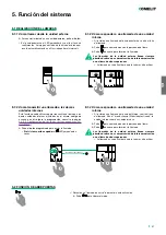
Page 97: ...función puede utilizarse para transmitir una llamada a las demás unidades internas ajustadas en el mismo código de usuario o en otro para la programación consulte la página 88 4 2 Configuración de las teclas táctiles capacitivas Art Ex 7000H Pulse el botón programado para enviar la llamada Si el sistema está ocupado el LED parpadeará 4 veces 5 1 4 Cómo responder a una llamada de una unidad interna...

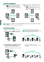
Page 98: ...e nuevo para desplazarse por varias cámaras Si hay una llamada en curso con una unidad externa NO será posible pasar de una unidad externa a otra 5 4 1 Cómo visualizar en el videoportero la imagen transmitida desde la cámara de CCTV Durante una llamada en curso o durante la autoactiva ción Pulse el botón programado para visualizar en el monitor la imagen transmitida desde la cámara de CCTV Púlselo...

Page 99: ...ÓN DEL ABREPUERTAS AUTOMÁTICO MODO DOCTOR D set to 3 Sec Pulse el botón programado durante 3 s para desactivar activar el abrepuertas automático 3 parpadeos cada 5 s del LED indican que el abrepuertas automático está activo 5 7 ACTIVACIÓN DESACTIVACIÓN DEL MODO DE RESPUESTA AUTOMÁTICA 10 Sec Pulse durante 10 segundos para activar desactivar el modo de respuesta automática Se oirá un tono de confir...

Page 100: ...100 ES 5 8 REGULACIÓN DEL BRILLO 5 9 CONTROL DE VOLUMEN DEL ALTAVOZ Para aumentar el brillo gire en el sentido de las agujas del reloj Para aumentar el volumen gire en el sentido de las agujas del reloj ...

Page 101: ... para cierres de 12 VCA CC impedancia máxima 18 ohmios Abrepuertas contacto de relé C NO 10 A a 12 24 V CA V CC Control de volumen del altavoz Sí Control de volumen del micrófono Sí Grado de protección IP IP54 Temperatura de funcionamiento 13 F 131 F 25 C 55 C Humedad de funcionamiento HR máx 0 95 Clase ambiental IV para utilizar al aire libre donde los componentes del sistema están totalmente exp...

Page 102: ...íquidos sobre ninguna parte del equipo Daños que requieren servicio la unidad debe ser revisada por personal de servicio cualificado cuando El cable de alimentación o el enchufe se haya dañado o Hayan caído objetos o se haya derramado líquido sobre el equipo o El equipo haya estado expuesto a la lluvia o El equipo no parezca funcionar con normalidad o muestre un marcado cambio de rendimiento o El ...

Page 103: ...a en el distribuidor Para todas las devoluciones se necesita una prueba de compra por parte del distribuidor en forma de factura Política de RMA DEVOLUCIÓN 1 Antes de solicitar un número RMA el instalador deberá llamar a nuestra línea de asistencia técnica para verificar el estado del producto así como con fines de solución de problemas para que Comelit determine si es preciso emitir un RMA 2 Si e...

Page 104: ...1ed 09 2022 cod 2G40002789 w w w c o m e l i t g r o u p c o m Via Don Arrigoni 5 24020 Rovetta BG Italy C E R T I F I E D M A N A G E M E N T S Y S T E M S ...

Reviews: