background image

POWER SUPPLIES AND ACCESSORIES

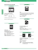
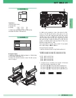
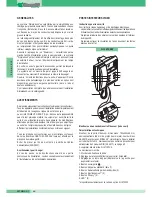
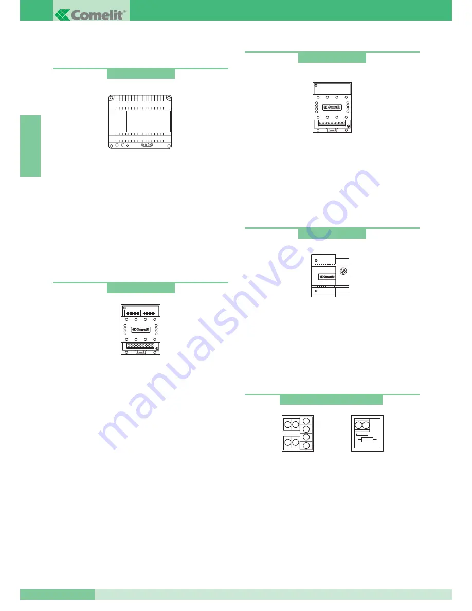
Transformer for Mixer-power supply
65VA Transformer. (T 1 min. on / 5 min. off).
Primary: 230VAC 
Secondary:

OUT1:     36VAC         1.5A
OUT2:     14VAC            1A

The transformer is equipped with internal protection PTC.

Dimensions: 107x90x60 (8 DIN modules).

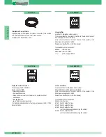
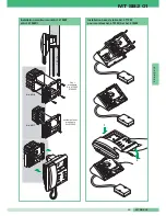
Switching device
Power supply 12VAC-20VDC.
Dimensions: 66x85x35mm (4 DIN modules).
Terminals for system connection:
~ ~ *

12VAC-20VDC power supply.

LS LS

secondary external unit bus line input.

LP LP

main external unit bus line input.

LM LM

riser bus line output.

For programming switching device, see page 40.

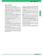
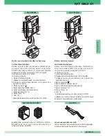
Power supply for additional monitor
Power supply 15VA (interm.).
Input: 230VAC 
Output:

0- 20VDC       700mA

The transformer is equipped with internal protection PTC.
Dimensions: 87x105x65 (5 DIN modules).

Art. 1246

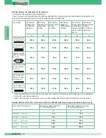
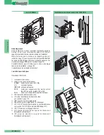
Line branch and termination terminal
See page 42 for configuration of Art. 1216 according to the 
cable used.
Terminals for system connection:
Lin Lin:

riser line input.

Lout Lout:  riser line output.
LM LM: 

riser line branched towards the monitor/telephone.

+  +:

power supply connection terminals for compatibility 
with Simplebus1 systems.

Art. 1212/B 

Relay
12-24V DC-AC 5A relay for general uses. Can be controlled directly
from the call repetition output of bracket Art. 4714W/2 or telephones
Art. 2428W. Dimensions: 66x85x35 mm (4 DIN modules). 
Terminals for system connection:
+  -

power supply relay.

C-NO-NC relay contacts.

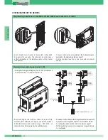
Art. 1122/A 

Art. 1214/2 and Art. 1216 

Art. 1214/2

Art. 1216 

Art. 1224 

GROUP S.P.A.

MT SB2 01

34

ENGLISH

Summary of Contents for MT SB2 01

Page 1: ...ico Digitale a 2 fili Digital video door entry system with 2 wires Système visiophonique numérique à 2 fils Tweedraads digitaal video intercom systeem 02 2004 MT SB2 01 TECHNICAL MANUAL MANUALE TECNICO MANUEL TECHNIQUE TECHNISCHE HANDLEIDING GB I F NL ...

Page 2: ... 6 POSTAZIONI ESTERNE pag 7 ALIMENTATORI E ACCESSORI pag 12 REGOLE DI INSTALLAZIONE pag 15 CONFIGURAZIONE DEI DISPOSITIVI pag 18 NOTE DI FUNZIONAMENTO pag 21 SCHEMI DI COLLEGAMENTO pag 88 VARIANTI AGLI SCHEMI BASE DI COLLEGAMENTO pag 98 Sistema Simplebus2 MT SB2 01 1 MT SB2 01 I T A L I A N O ...

Page 3: ...e effettuate da altri a qualunque titolo e scopo per l uso di accessori e materiali non originali Effettuare le installazioni in conformità alle norme vigenti Tutti i prodotti sono conformi alle prescrizioni delle direttive CEE 73 23 89 336 e ciò è attestato dalla presenza della marcatura CE sugli stessi Evitare di porre i fili di montante in prossimità di cavi di alimentazione 220 380V Avvertenze...

Page 4: ...asso monitor Art 4700W Monitor serie Videocom da parete Caratteristiche tecniche Monitor della serie Videocom di dimensioni 193x223x65 da parete colore bianco RAL9010 con schermo B W da 4 5 visione diretta Da completare con staffa Art 4714W 2 Il monitor è completo di 1 Ganci di fissaggio alla staffa 2 Regolazione luminosità ruotare per variare l intensità 3 Regolazione volume chiamata spostare ver...

Page 5: ...o 0 20V morsetti connessione Art 1212 B L L connessione linea bus CFP CFP ingresso chiamata da piano P1 C1 pulsante per usi vari Per avere un contatto pulito NO tagliare i cavallotti CV3 e CV4 S S morsetti per dispositivo ripetizione di chiamata 3 CV5 Cavallotto chiusura video 4 JP1 jumper di abilitazione richiesta video vedi variante F pag 110 5 CN2 connettore per programmazione 6 Dip switches pe...

Page 6: ...olo per monitor Art 4700W Art 4700W 4700W I Per monitor Installazione monitor Art 4700W e Art 4700W I a parete 2 1 4 3 1 2 Installazione base da tavolo Art 4712W per monitor Art 4701W A e Art 4700W MT SB2 01 5 MT SB2 01 I T A L I A N O ...

Page 7: ...a pag 18 Da utilizzare solo per impianti audio Caratteristiche tecniche 1 Pulsante apriporta 2 Pulsante chiamata centralino pulsante per usi vari presente in morsettiera AB 3 Morsetti connessione impianto L L connessione alla linea bus CFP CFP ingresso chiamata da piano AB pulsante normalmente dedicato a servizi vari Per avere contatto pulito NO tagliare i cavallotti CV1 e CV2 4 Dip switches per i...

Page 8: ...2 possono essere utilizzate postazioni esterne della Serie Powercom Vandalcom e Logicom Per Vandalcom e Logicom rifarsi al foglio tecnico FT SB 01 e al Catalogo 50 Portiere audio Serie Powercom Composto dagli Art 3320 Art 1602 Portiere citofonico con morsettiera e doppio amplificatore altoparlante stagno e microfono ad electret Volume microfono ed altoparlante regolabili frontalmente sull Art 1602...

Page 9: ...dulo rubrica portanomi elettronica con display grafico 128x64 dots Memorizza 400 nomi di utenti Lo scorrimento dei nomi avviene agendo su due pulsanti di ricerca Una volta visualizzato il nome dell utente desiderato basta premere il pulsante di chiamata L inserimento degli utenti avviene in modo semplice mediante programmatore Art 1230 oppure con il software per PC Art 1249 Dimensioni 112x89 5x40 ...

Page 10: ... 160 165 cm Altezza scatola incasso Come accostare più scatole Fissaggio del telaio su scatola da incasso Fissaggio del telaio su custodia da parete Collegamento cavetto a 4 poli Cablaggio morsettiera inserita o estratta MT SB2 01 9 MT SB2 01 I T A L I A N O ...

Page 11: ...regolazioni gruppo audio video Inserimento moduli 2 3 5 1 4 Posizione alternativa del microfono Montaggio Smontaggio frontalini Fissaggio cornice Carla Rossi Montaggio Smontaggio cartellini open close GROUP S P A MT SB2 01 10 I T A L I A N O ...

Page 12: ...tto a 4 poli 10 Inserimento modulo 2 1 10 Estrazione porta cartellino 15 Inserimento estrazione cartellino Istruzioni per montaggio moduli informativi Art 3326 Art 3344 e Art 3346 MT SB2 01 11 MT SB2 01 I T A L I A N O ...

Page 13: ...ta 0 20VDC 700mA Il trasformatore è equipaggiato con PTC interno di protezione Dimensioni 87x105x65 5 moduli DIN Art 1246 Morsetto di derivazione e terminazione di linea Vedi pag 20 per configurazione Art 1216 a seconda del cavo utilizzato Morsetti connessione impianto Lin Lin ingresso linea montante Lout Lout uscita linea montante LM LM linea montante derivata verso il monitor citofono morsetti c...

Page 14: ...serire la linea in ingresso dal posto esterno e quindi dare alimentazione anche al modulo Miscelatore alimentatore Art 4896 Il dispositivo consente di alimentare al massimo un monitor ed è in grado di gestire al MAX 100 utenti Morsetti connessione impianto 1 Lin Lin connessione alla linea proveniente dal posto esterno 2 0V 36V connessione ai morsetti OUT1 del trasformatore Art 1246 0V 14V connessi...

Page 15: ... connessione impianto Lin Lin ingresso linea montante L1 L1 uscita derivazione1 di montante L2 L2 uscita derivazione2 di montante L3 L3 uscita derivazione3 di montante tagliare la resistenza prima di inserire i cavi L4 L4 uscita derivazione4 di montante tagliare la resistenza prima di inserire i cavi Art 4834 2 Cavo comelit Simplebus2 Cavo specifico per impianti Simplebus2 è composto da due condut...

Page 16: ...più diramazioni fino a 16 è necessario mettere in cascata due Art 4834 2 L Art 4834 2 aggiunto deve essere preceduto dal rispettivo amplificatore di segnale video Art 4833 A vedi variante SB2 C pag 104 Si possono inserire sino al MAX 2 Art 4834 2 in cascata Il numero MAX di utenti collegabili ad un singolo Miscelatore alimentatore Art 4896 è di 100 indipendentemente che siano divisi su un singolo ...

Page 17: ...833 A e Miscelatore Art 4896 Distanza MAX tra posto esterno e Miscelatore o amplifcatore Art 4833 A con un Art 4834 2 inserito 60 m 40 m 30 m 40 m 80 m 150 m 150 m 150 m 100 m 40 m H Distanza MAX tra morsetto di derivazione Art 1214 2 e posto interno Cavo Comelit Art 4577 sez 1 mm2 Ø 1 2 mm Cavo bifilare sez 1 5 mm2 Ø 1 4 mm Cavo intrecciato e schermato sez 1 mm2 Ø 1 2 mm Sezione del conduttore 4 ...

Page 18: ...Figure per le distanze MT SB2 01 17 MT SB2 01 I T A L I A N O ...

Page 19: ... una coppia di Dip switches ad 8 selettori vedi figura I due Dip switches definiscono il range minimo MIN e massimo MAX di codici che possono essere riconosciuti dallo scambio Si ricordi che i Dip switches MIN e MAX definiscono rispettivamente i codici utente più basso e più alto collegabili al montante Per l impostazione dei valori desiderati si faccia riferimento alla tabella di pag 19 Scambi di...

Page 20: ...153 1 4 5 8 213 1 3 5 7 8 34 2 6 94 2 3 4 5 7 154 2 4 5 8 214 2 3 5 7 8 35 1 2 6 95 1 2 3 4 5 7 155 1 2 4 5 8 215 1 2 3 5 7 8 36 3 6 96 6 7 156 3 4 5 8 216 4 5 7 8 37 1 3 6 97 1 6 7 157 1 3 4 5 8 217 1 4 5 7 8 38 2 3 6 98 2 6 7 158 2 3 4 5 8 218 2 4 5 7 8 39 1 2 3 6 99 1 2 6 7 159 1 2 3 4 5 8 219 1 2 4 5 7 8 40 4 6 100 3 6 7 160 6 8 220 3 4 5 7 8 41 1 4 6 101 1 3 6 7 161 1 6 8 221 1 3 4 5 7 8 42 2...

Page 21: ...on lo stesso codice assegnato al citofono o monitor secondo la corrispondenza descritta nella tabella di programmazione a pag 19 4 Premere il pulsante che si desidera associare alla chiamata del citofono L avvenuta programmazione viene segnalata con un tono di conferma 5 Al termine della programmazione rimettere i jumper nelle posizioni iniziali PR su PR e P O su OCC Impostazione posto esterno pri...

Page 22: ...or si ha la possibilità di visualizzare sul monitor l immagine prima da uno poi dall altro dei due posti esterni funzione di bascula tra due ingressi Per variare la luminosità del monitor agire sulla rotella di regolazione posta nel lato inferiore Per variare il volume della suoneria di chiamata agire sull apposito deviatore graduato collocato sul lato inferiore del monitor Con la scheda opzionale...

Page 23: ......

Page 24: ... TELEPHONE HANDSETS page 28 EXTERNAL UNITS page 29 POWER SUPPLIES AND ACCESSORIES page 34 INSTALLATION RULES page 37 CONFIGURATION OF THE DEVICES page 40 NOTES ON OPERATION page 43 WIRING DIAGRAMS page 88 VARIANTS TO THE BASIC WIRING DIAGRAMS page 94 Simplebus2 System E N G L I S H MT SB2 01 23 MT SB2 01 ...

Page 25: ...r incorrect use of the apparatus for modifications made by third parties for any reason and purpose for the use of accessories and materials which are not originals Carry out installation in compliance with the standards in force All the products conform to the prescriptions of the EEC 73 23 89 336 Directives and this is certified by the CE mark on them Avoid placing the riser wires near power sup...

Page 26: ...for flush mounting monitor Art 4700W Videocom series surface mounted Monitor Technical characteristics Videocom series monitor with dimensions 193x223x65 surface mounted white RAL9010 with 4 5 direct vision B W screen To be completed with bracket Art 4714W 2 The monitor is complete with 1 Hooks for fixing to the bracket 2 Brightness control turn to vary the brightness 3 Call tone volume control mo...

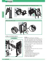
Page 27: ...n terminals 0 20V connection terminals Art 1212 B L L bus line connection CFP CFP local floor call input P1 C1 push button for various uses To have a clean NO contact cut the CV3 and CV4 bridges S S terminals for call repeater device 3 CV5 Bridge for closing video 4 JP1 jumper for enabling video request see variant F on page 110 5 CN2 connector for programming 6 Dip switches for programming user c...

Page 28: ...00W I Per monitor Installation of surface mounted monitor Art 4700W and Art 4700W I 2 1 4 3 1 2 Installation of desk convertion kit Art 4712W for monitor Art 4701W A and Art 4700W For monitor Art 4700W 4700W I only for monitor Art 4700W MT SB2 01 27 MT SB2 01 E N G L I S H ...

Page 29: ...on page 40 Only to be used for audio systems Technical characteristics 1 Door opening push button 2 Switchboard call push button push button for various uses present in terminal board AB 3 Terminal connection System with L L connection to the line bus CFP CFP input floor door call AB push button normally dedicated to various services To have a clean NO contact cut bridges CV1 and CV2 4 Dip switche...

Page 30: ...rcom Vandalcom and Logicom Series can be used For Vandalcom and Logicom refer to technical sheet FT SB 01 and to Catalogue 50 Powercom Series speaker unit Consisting of Art 3320 Art 1602 Speaker unit with terminal board and double amplifier watertight loudspeaker and electret microphone Microphone and loudspeaker volume adjustable from the front on Art 1602 see page 32 possibility of rear adjustme...

Page 31: ...It is complete with electronic name directory which memorises 400 user names Name scrolling is carried by using two search push buttons or by entering the initials of the name or user code directly Once the desired user name is displayed simply press the call push button User programming is carried out in a simple way using programmer art 1230 or with the software for PC art 1249 Dimensions 112x18...

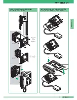
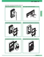
Page 32: ...m Height of flush mounted box How to place several boxes together Fixing the frame onto the flush mounting box Fixing the frame onto the surface mounted housing Connection of 4 pole cable Cabling terminal board inserted or withdrawn MT SB2 01 31 MT SB2 01 E N G L I S H ...

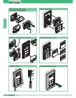
Page 33: ...mbly connections and adjustments Insertion of modules 2 3 5 1 4 Alternative position of the microphone Assembly Dismantling faces Fixing the cornice Carla Rossi Assembly Dismantling labels open close GROUP S P A MT SB2 01 32 E N G L I S H ...

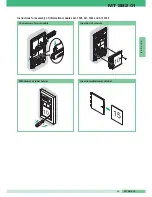
Page 34: ...pole cable 10 Insertion of module 2 1 10 Withdrawal of label holder 15 Insertion withdrawal of label Instructions for assembly of information modules Art 3326 Art 3344 and Art 3346 MT SB2 01 33 MT SB2 01 E N G L I S H ...

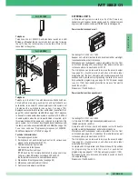
Page 35: ...utput 0 20VDC 700mA The transformer is equipped with internal protection PTC Dimensions 87x105x65 5 DIN modules Art 1246 Line branch and termination terminal See page 42 for configuration of Art 1216 according to the cable used Terminals for system connection Lin Lin riser line input Lout Lout riser line output LM LM riser line branched towards the monitor telephone power supply connection termina...

Page 36: ... to allow re setting Insert the line on input from the external unit and then switch on the power from Art 1246 to the Mixer power supply module Art 4896 The device allows a maximum of one monitor to be supplied and is able to manage a MAX of 100 users Terminals for system connection 1 Lin Lin connection to the line coming from the external unit 2 0V 36V connection to terminals OUT1 of transformer...

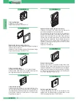
Page 37: ...dules Terminals for system connection Lin Lin riser line input L1 L1 branch output1 of riser L2 L2 branch output2 of riser L3 L3 branch output3 of riser cut the resistance before inserting the cables L4 L4 branch output4 of riser cut the resistance before inserting the cables Art 4834 2 Simplebus2 Comelit Cable Specific cable for Simplebus 2 systems consists of two twisted red and black conductors...

Page 38: ...where several branches are needed up to 16 it is necessary to put two Arts 4834 2 in cascade The additional Art 4834 2 must be preceded by the relative video signal amplifier Art 4833 A see variant SB2 C on page 104 A MAX of 2 Arts 4834 2 in cascade can be inserted The MAX number of users which can be connected to a single Mixer power supply Art 4896 is 100 regardless of whether they are divided o...

Page 39: ...and Mixer Art 4896 Max distance between external unit and Mixer or amplifier Art 4833 A with a Art 4834 2 inserted 60 m 40 m 30 m 40 m 80 m 150 m 150 m 150 m 100 m 40 m H Max distance between terminal of branch Art 1214 2 and internal unit Comelit cable Art 4577 1mm2 cross sect Ø1 2mm Two wire cable 1 5 mm2 cross sect Ø 1 4 mm Braided and shielded cable 1 mm2 cross sect Ø 1 2 mm Cross section of t...

Page 40: ...Figures showing distances MT SB2 01 39 MT SB2 01 E N G L I S H ...

Page 41: ...8 selectors see figure The two Dip switches define the minimum and maximum range MIN MAX of codes which can be recognised by the switching device Remember that the MIN and MAX Dip switches define the lowest and highest user codes respectively which can be connected to the riser For setting the values desired refer to the table on page 41 Distinct switching devices must manage code ranges which are...

Page 42: ... 6 93 1 3 4 5 7 153 1 4 5 8 213 1 3 5 7 8 34 2 6 94 2 3 4 5 7 154 2 4 5 8 214 2 3 5 7 8 35 1 2 6 95 1 2 3 4 5 7 155 1 2 4 5 8 215 1 2 3 5 7 8 36 3 6 96 6 7 156 3 4 5 8 216 4 5 7 8 37 1 3 6 97 1 6 7 157 1 3 4 5 8 217 1 4 5 7 8 38 2 3 6 98 2 6 7 158 2 3 4 5 8 218 2 4 5 7 8 39 1 2 3 6 99 1 2 6 7 159 1 2 3 4 5 8 219 1 2 4 5 7 8 40 4 6 100 3 6 7 160 6 8 220 3 4 5 7 8 41 1 4 6 101 1 3 6 7 161 1 6 8 221 ...

Page 43: ...r of the audio module with the same code assigned to the telephone or monitor according to the correspondence described in the programming table on page 41 4 Press the push button to be associated with the telephone call A confirmation tone signals that programming has taken place 5 On completion of programming put the jumpers back into their initial positions PR on PR and P O on OCC Setting main ...

Page 44: ... 2 of monitor self ignition in succession there is the possibility of displaying first one image and then the other of the two external units on the monitor alternating function between two entrances To vary the brightness of the monitor use the adjustment wheel at the bottom To vary the call tone volume use the special graduated deviator located on the bottom of the monitor It is possible to set ...

Page 45: ......

Page 46: ...O page 50 PLAQUES DE RUE page 51 ALIMENTATIONS ET ACCESSOIRES page 56 REGLES D INSTALLATION page 59 CONFIGURATION DES DISPOSITIFS page 62 NOTES DE FONCTIONNEMENT page 65 SCHEMAS DE CONNEXION page 88 VARIANTES AUX SCHEMAS DE CONNEXION DE BASE page 98 Système Simplebus2 MT SB2 01 45 MT SB2 01 F R A N Ç A I S ...

Page 47: ...lisation impropre des appareils de modifications effectuées par d autres à quelque titre et pour quelque objectif que ce soit et de l emploi d accessoires et de matériaux non d origine Effectuer les installations conformément aux normes en vigueur Tous les produits sont conformes aux prescriptions contenues dans les directives CEE 73 23 89 336 et cela est attesté par la présence du marquage CE Evi...

Page 48: ...ie civile 3 modules DIN utilisable pour encastrer le moniteur Art 4700W Moniteur mural série Videocom Caractéristiques techniques Moniteur de la série Videocom dimensions 193x223x65 mm mural couleur blanc RAL9010 avec écran en N B de 4 5 vision directe A compléter avec la bride Art 4714W 2 Le moniteur est muni de 1 Crochets de fixation à la bride 2 Réglage de la luminosité tourner pour varier l in...

Page 49: ...tallation 0 20V bornes de connexion Art 1212 B L L connexion ligne bus CFP CFP entrée appel du palier P1 C1 bouton pour usages divers Pour avoir un contact libre NO couper les cavaliers CV3 et CV4 S S bornes pour le dispositif de répétition de l appel 3 CV5 Cavalier de débranchement vidéo 4 JP1 jumper de validation de la demande vidéo voir variante F page 110 5 CN2 connecteur pour la programmation...

Page 50: ...W 4700W I Per monitor Installation moniteur mural Art 4700W et Art 4700W I 2 1 4 3 1 2 Installation base de table Art 4712W pour moniteur Art 4701W A et Art 4700W Pour moniteurs Art 4700W 4700W I seulement pour moniteurs Art 4700W MT SB2 01 49 MT SB2 01 F R A N Ç A I S ...

Page 51: ...arlophonique Art 2408W A 2428W et bride Art 4714W 2 à la page 62 A utiliser uniquement pour des installations audio Caractéristiques techniques 1 Bouton ouvre porte 2 Bouton d appel du standard bouton pour usages divers présent dans la boîte à bornes AB 3 Bornes de connexion à l installation L L connexion à la ligne bus CFP CFP entrée appel du palier AB bouton normalement destiné à des services di...

Page 52: ...oir page 63 5 Trimmer de réglage du volume du micro 6 Trimmer de réglage du volume de la sonnerie 5 6 1 2 4 3 MIC Art 2410W Art 2428W PLAQUES DE RUE Les installations Simplebus2 peuvent monter des plaques de rue Série Powercom Vandalcom et Logicom Pour les séries Vandalcom et Logicom se référer à la fiche technique FT SB 01 et au Catalogue 50 HP micro Série Powercom Composé des Art 3320 Art 1602 H...

Page 53: ...e défilement des noms s effectue en appuyant sur deux boutons de recherche Après affichage du nom de l usager désiré il suffira d appuyer sur le bouton d appel La programmation des noms des usagers s effectue aisément au moyen du programmateur art 1230 ou du logiciel pour micro ordinateur P C Art 1249 Dimensions 112x89 5x40 mm Art 3342 Art 3346 Art 3340 Boîtiers à encastrer Disponibles pour 1 2 et...

Page 54: ...60 165 cm Hauteur boîtier à encastrer Comment associer plusieurs boîtiers Fixation du petit câble sur le boîtier à encastrer Fixation du cadre sur le boîtier mural Connexion cadre à 4 pôles Câblage boîte à bornes insérée ou retirée MT SB2 01 53 MT SB2 01 F R A N Ç A I S ...

Page 55: ...xions et réglages groupe audio vidéo Introduction modules 2 3 5 1 4 Position alternative du micro Pose dépose éléments frontaux Fixation cadre Carla Rossi Pose dépose étiquettes open close GROUP S P A MT SB2 01 54 F R A N Ç A I S ...

Page 56: ...4 pôles 10 Introduction module 2 1 10 Retrait porte étiquette 15 Introduction retrait étiquette Instructions pour le montage des modules d information Art 3326 Art 3344 et Art 3346 MT SB2 01 55 MT SB2 01 F R A N Ç A I S ...

Page 57: ...formateur est équipé d un PTC intérieur de protection Dimensions 87x105x65 5 modules DIN Art 1246 Borne de dérivation et borne de terminaison de ligne Voir page 64 pour la configuration de l Art 1216 selon le câble utilisé Bornes de connexion à l installation Lin Lin entrée ligne montant Lout Lout sortie ligne montant LM LM ligne montant dérivée vers le moniteur combiné parlophonique bornes connex...

Page 58: ...ndant environ une minute Brancher la ligne en entrée de la plaque de rue et alimenter ensuite également le module mélangeur Art 4896 Le dispositif consent d alimenter au maximum un moniteur et de gérer au maximum MAX 100 usagers Bornes de connexion de l installation 1 Lin Lin connexion à la ligne venant de la plaque de rue 2 0V 36V connexion aux bornes OUT1 du transformateur Art 1246 0V 14V connex...

Page 59: ...n Lin Lin entrée ligne montant L1 L1 sortie dérivation 1 du montant L2 L2 sortie dérivation 2 du montant L3 L3 sortie dérivation 3 du montant couper la résistance avant d introduire les câbles L4 L4 sortie dérivation 4 du montant couper la résistance avant d introduire les câbles Art 4834 2 Câble Comelit Simplebus2 Câble spécial pour les installations Simplebus2 il se compose de deux conducteurs a...

Page 60: ...usqu à 16 il faudra mettre en cascade deux Art 4834 2 L Art 4834 2 additionnel doit être précédé de son amplificateur de signal vidéo correspondant Art 4833 A voir variante SB2 C page 104 Possibilité d insérer jusqu au MAX 2 Art 4834 2 en cascade Le nombre MAX d usagers pouvant être branché à un seul mélangeur alimentation Art 4896 est de 100 usagers indépendamment qu ils soient distribués sur un ...

Page 61: ... 4833 A et le mélangeur Art 4896 Distance MAX entre la plaque de rue et le mélangeur ou l amplificateur Art 4833 A avec un Art 4834 2 branché 60 m 40 m 30 m 40 m 80 m 150 m 150 m 150 m 100 m 40 m H Distance MAX entre la borne de dérivation 1 Art 1214 2 et le poste intérieur Câble Comelit Art 4577 sect 1 mm2 Ø 12 10 Câble bifilaire sect 1 5 mm2 Ø 14 10 Câble tressé et blindé sect 1 mm2 Ø 12 10 Sect...

Page 62: ...Figures pour les distances MT SB2 01 61 MT SB2 01 F R A N Ç A I S ...

Page 63: ...rs voir figure Les deux dip switches définissent la plage minimum MIN et maximum MAX des codes pouvant être reconnus par le commutateur N oubliez pas que les dip switches MIN et MAX définissent respectivement le code usager le plus bas et le code usager le plus haut pouvant être branchés au montant Pour programmer les valeurs désirées se référer au tableau de la page 63 Des commutations distinctes...

Page 64: ... 153 1 4 5 8 213 1 3 5 7 8 34 2 6 94 2 3 4 5 7 154 2 4 5 8 214 2 3 5 7 8 35 1 2 6 95 1 2 3 4 5 7 155 1 2 4 5 8 215 1 2 3 5 7 8 36 3 6 96 6 7 156 3 4 5 8 216 4 5 7 8 37 1 3 6 97 1 6 7 157 1 3 4 5 8 217 1 4 5 7 8 38 2 3 6 98 2 6 7 158 2 3 4 5 8 218 2 4 5 7 8 39 1 2 3 6 99 1 2 6 7 159 1 2 3 4 5 8 219 1 2 4 5 7 8 40 4 6 100 3 6 7 160 6 8 220 3 4 5 7 8 41 1 4 6 101 1 3 6 7 161 1 6 8 221 1 3 4 5 7 8 42 ...

Page 65: ...attribué au combiné parlophonique ou au moniteur selon la correspondance décrite dans le tableau de programmation à la page 63 4 Appuyer sur le bouton que l on désire associer à l appel du combiné parlophonique La réalisation de la programmation est signalée par un bip de confirmation 5 A la fin de la programmation replacer les jumpers dans leurs positions initiales PR sur PR et P O sur OCC Progra...

Page 66: ...t d afficher l image d abord de l un ensuite de l autre des deux plaques de rue fonction de bascule entre deux entrées Pour varier la luminosité du moniteur intervenir sur la molette de réglage placée sur la partie inférieure Pour varier le volume de la sonnerie d appel intervenir sur le déviateur gradué spécial placé sur la partie inférieure du moniteur La carte en option Art 4703 permet de progr...

Page 67: ......

Page 68: ...ONS pag 72 ENTREEPANELEN pag 73 VOEDINGEN EN ACCESSOIRES pag 78 INSTALLATIEVOORSCHRIFTEN pag 81 CONFIGURATIE VAN DE APPARATUUR pag 84 WERKING pag 87 AANSLUITSCHEMA S pag 88 VARIANTEN VAN DE STANDAARD AANSLUITSCHEMA S pag 98 Simplebus2 Systeem MT SB2 01 67 MT SB2 01 N E D E R L A N D S ...

Page 69: ...aangebrachte wijzigingen voor wat voor doeleinde dan ook en het gebruik van niet originele accessoires en materiaal Installeer het systeem in overeenstemming met de geldende normen Alle producten zijn in overeenstemming met de voorschriften van de richtlijnen CEE 73 23 89 336 en dit wordt aangetoond door het CE keurmerk op de apparaten Plaats de bedrading van de stamleiding niet in de buurt van vo...

Page 70: ...tor art 4700W Wandmonitor serie Videocom Technische gegevens Monitor van de serie Videocom met afmetingen 193x223x65 voor aan de wand wit RAL9010 met B W 4 5 direct zicht scherm Te completeren met aansluitgrondplaat art 4714W 2 De monitor is compleet met 1 Bevestigingshaken aan de aansluitgrondplaat 2 Afstelling van de helderheid draaien om de lichtsterkte te veranderen 3 Afstelling van het belvol...

Page 71: ...gen op de klemmen 0 20V aansluiting art 1212 B L L aansluiting buslijn CFP CFP Ingang voor etagebel drukknop P1 C1 Voor een potentiaal vrij contact knip de bruggen CV3 en CV4 door S S uitgang voor extra bel 3 CV5 Brug voor afsluiten videosignaal 4 JP1 jumper voor activering van passieve beeldoproep bij secundaire monitoren zie variant F pag 110 5 CN2 steker voor programmering 6 Dipswitches voor he...

Page 72: ...0W I Per monitor Installatie wandmonitor art 4700W en art 4700W I 2 1 4 3 1 2 Installatie van bureausteun art 4712W voor monitor art 4701W A en art 4700W MT SB2 01 71 MT SB2 01 N E D E R L A N D S Voor monitor art 4700W 4700W I Alleen voor monitor art 4700W art 4514 art 4517 ...

Page 73: ...audio installaties Technische gegevens 1 Deuropeningsknop 2 Knop voor het bellen naar de portierscentrale drukknop voor verschillende doeleinden aansluitingen AB 3 Aansluitingen op de klemmen L L aansluiting buslijn CFP CFP ingang etagebel AB Aansluitingen drukknop voor diverse doeleinden Voor een potentieelvrij NO contact de draadbruggen CV1 en CV2 doorknippen 4 Dipswitches voor het instellen van...

Page 74: ...om Vandalcom en Logicom gebruikt worden Voor Vandalcom en Logicom wordt er verwezen naar het technisch blad FT SB 01 en naar de Catalogus 50 Audio luidsprekerunit Serie Powercom Bestaat uit art 3320 art 1602 Luidsprekerunits met aansluitblok en dubbele versterker waterdichte luidspreker en electretmicrofoon Het volume van de microfoon en van de luidspreker kan zowel vanaf de voorkant als vanaf de ...

Page 75: ...dots Kan maximaal 400 gebruikersnamen opslaan Om een naam op te zoeken kan worden gescrolled d m v 2 drukknoppen Als de juiste naam op het display verschijnt kan eenvoudig op de beltoets gedrukt worden Het programmeren is eenvoudig door het gebruik van een afstandbediening art 1230 of met de software voor PC art 1249 Afmetingen 112x89 5x40 mm Drukknopmodulen Beldrukker module uitgevoerd met micros...

Page 76: ...160 165 cm Hoogte inbouwdoos Hoe meerdere dozen naast elkaar te plaatsen Bevestiging van het frame op de inbouwdoos Bevestiging van het frame op de opbouw behuizing Aansluiting 4 polige kabel Aansluitblok plaatsen of verwijderen MT SB2 01 75 MT SB2 01 N E D E R L A N D S ...

Page 77: ...ingen audio video systeem Aanbrengen van de modulen 2 3 5 1 4 Andere positie van de microfoon Montage Demontage voorpanelen Bevestiging sierrand Carla Rossi Aanbrengen verwijderen naamkaartjes open close GROUP S P A MT SB2 01 76 N E D E R L A N D S ...

Page 78: ...ge kabel 10 Aanbrengen van de module 2 1 10 Verwijdering kaartjeshouder 15 Kaartje aanbrengen verwijderen Montage instructies informatieve modulen art 3326 art 3344 en art 3346 MT SB2 01 77 MT SB2 01 N E D E R L A N D S ...

Page 79: ...0 20VDC 700mA De transformator is uitgerust met interne PTC beveiliging Afmetingen 87x105x65 5 DIN modulen art 1246 Aftakblok en Afsluitblok Zie pag 86 voor de configuratie van art 1216 i c m de gebruikte kabel Aansluitklemmen Lin Lin ingang stamleiding Lout Lout uitgang stamleiding LM LM Aftakking naar de monitor deurtelefoon klemmen voor aansluiting voeding voor compatibiliteit met Simplebus1 in...

Page 80: ...ren Schakel eerst het entreepaneel in en zet daarna spanning op de voedingsmixer art 4896 Met deze voedingsmixer kan maximaal één monitor tegelijk gevoed worden en is in staat MAX 100 gebruikers te beheren Aansluitklemmen 1 Lin Lin aansluiting op de lijn afkomstig van entreepanele e l en 2 0V 36V aansluiting op de klemmen OUT1 van de transformator art 1246 0V 14V aansluiting op de klemmen OUT2 van...

Page 81: ... buslijn L1 L1 uitgang buslijn 1 L2 L2 uitgang buslijn 2 L3 L3 uitgang buslijn 3 weerstand afknippen alvorens de draad aan te brengen L4 L4 uitgang buslijn 4 weerstand afknippen alvorens de draad aan te brengen art 4834 2 Comelit Simplebus2 kabel Speciale kabel voor Simplebus2 installaties bestaat uit een rode en zwarte getwiste ader 1 mm2 Leverbaar in rollen van 100 m en haspels van 500 m Relais ...

Page 82: ...worden aangesloten als er meer aftakkingen nodig zijn max 16 dienen er twee buslijnverdelers art 4834 2 in cascade te worden aangesloten De uitgang van de eerste buslijnverdeler dient te worden versterkt door de versterker 4833 A zie variant SB2 C pag 104 Er kunnen MAX 2 buslijnverdelers art 4834 2 in cascade geschakeld worden Het MAX aantal gebruikers dat op één voedingsmixer art 4896 aangesloten...

Page 83: ... versterker art 4833 A met art 4834 2 60 m 40 m 30 m 40 m 80 m 150 m 150 m 150 m 100 m 40 m H MAX afstand tussen aftakblokje art 1214 2 en binnentoestel Comelit kabel art 4577 doorsn 1 mm2 Ø 1 2 mm Tweeaderige kabel doorsn 1 5mm2 Ø 1 4 mm Getwiste en afgescherm de kabel doorsn 1 mm2 Ø 1 2 mm Doorsnede van de ader 4 m 10 m 20 m 30 m 40 m 10 m 25 m 50 m 100 m 150 m F G MAX afstand tussen transformat...

Page 84: ...Afbeeldingen voor de afstanden MT SB2 01 83 MT SB2 01 N E D E R L A N D S ...

Page 85: ...8 schakelaars zie afbeelding Met de twee dipswitches kan de minimale MIN en de maximale MAX range van codes worden ingesteld op de selector Let op de MIN en de MAX dipswitches vertegenwoordigen de laagste en hoogste code die op deze buslijn kan worden aangesloten Om de waarden in te stellen verwijzen wij naar pag 85 Bij meerdere selektors mogen de codes elkaar niet overlappen PORTA PRINCIPALE DAL ...

Page 86: ...3 1 3 5 7 8 34 2 6 94 2 3 4 5 7 154 2 4 5 8 214 2 3 5 7 8 35 1 2 6 95 1 2 3 4 5 7 155 1 2 4 5 8 215 1 2 3 5 7 8 36 3 6 96 6 7 156 3 4 5 8 216 4 5 7 8 37 1 3 6 97 1 6 7 157 1 3 4 5 8 217 1 4 5 7 8 38 2 3 6 98 2 6 7 158 2 3 4 5 8 218 2 4 5 7 8 39 1 2 3 6 99 1 2 6 7 159 1 2 3 4 5 8 219 1 2 4 5 7 8 40 4 6 100 3 6 7 160 6 8 220 3 4 5 7 8 41 1 4 6 101 1 3 6 7 161 1 6 8 221 1 3 4 5 7 8 42 2 4 6 102 2 3 6...

Page 87: ...ls die op de corresponderende huistelefoon of monitor ingesteld is volgens de tabel op pag 85 4 Druk nu op de drukknop die op deze code moet worden geprogrammeerd Als de programmering wordt opgeslagen wordt dit bevestigd door een bevestigingstoon 5 Zet na de programmering de doorverbindingen weer in de oorspronkelijke posities PR op PR en P O op OCC Instellen als hoofdpaneel of secundaire ingang D...

Page 88: ... entreepanelen met camera geïnstalleerd zijn kunt u door knop 2 voor de beeldoproep van de monitor nogmaals in te drukken eerst het beeld van de ene ingang en dan van de andere ingang verkrijgen afwisselingfunctie tussen de twee ingangen De helderheid van de monitor kan worden veranderd door het stelwieltje aan de onderkant te gebruiken Het volume van de bel kan worden ingesteld door de schakelaar...

Page 89: ... porte audio Série Logicom Installatie 1 audio entreepaneel Serie Logicom SBC 01L I GB F NL Impianto 1 porta audio Serie Powercom System with 1 Powercom Series audio entrance Installation avec 1 porte audio Série Powercom Installatie 1 audio entreepaneel Serie Powercom SBC 01 I GB F NL GROUP S P A MT SB2 01 88 I T A L I A N O E N G L I S H F R A N Ç A I S N E D E R L A N D S A ...

Page 90: ... audio entreepaneel Serie Logicom 3040 3070 3042 3072 SBC 02L I GB F NL Impianto 2 porte audio digitali Serie Powercom 3340 3342 System with 2 Powercom Series digital audio entrances 3340 3342 Installation avec 2 portes audio numériques Série Powercom 3340 3342 Installatie 2 digitale audio entreepanelen Serie Powercom 3340 3342 SBC 02 I GB F NL MT SB2 01 89 MT SB2 01 I T A L I A N O E N G L I S H ...

Page 91: ...m with 1 Logicom Series video entrance Installation avec 1 porte vidéo Série Logicom Installatie 1 video entreepaneel Serie Logicom SB2V 01L I GB F NL GROUP S P A MT SB2 01 90 I T A L I A N O E N G L I S H F R A N Ç A I S N E D E R L A N D S A ...

Page 92: ...em with 1 Powercom Series video entrance Installation avec 1 porte vidéo Série Powercom Installatie 1 video entreepaneel Serie Powercom SB2V 01 I GB F NL MT SB2 01 91 MT SB2 01 I T A L I A N O E N G L I S H F R A N Ç A I S N E D E R L A N D S A ...

Page 93: ...N G L I S H F R A N Ç A I S N E D E R L A N D S A Impianto 2 porte video Serie Logicom System with 2 Logicom Series video entrances Installation avec 2 portes vidéo Série Logicom Installatie 2 video entreepanelen Serie Logicom SB2V 03L I GB F NL ...

Page 94: ... L I S H F R A N Ç A I S N E D E R L A N D S A Impianto 2 porte video Serie Powercom System with 2 Powercom Series video entrances Installation avec 2 portes vidéo Série Powercom Installatie 2 video entreepanelen Serie Powercom SB2V 03 I GB F NL ...

Page 95: ...4 I T A L I A N O E N G L I S H F R A N Ç A I S N E D E R L A N D S A Impianto con 1 porta video Serie Powercom e max 4 Miscelatori alimentatori Art 4896 System with 1 Powercom Series video entrance and MAX 4 Mixers power supplies Art 4896 Installation avec 1 porte vidéo Série Powercom et MAX 4 mélangeurs alimentations Art 4896 Installatie met 1 video entreepaneel Serie Powercom en MAX 4 voedingmi...

Page 96: ... L A N D S A Impianto con 2 porte video e centralino di portineria Art 1998 System with 2 video entrances and porter switchboard Art 1998 Installation avec 2 portes vidéo et un HP micro Art 1998 Installatie met 2 video entreepanelen en portierscentrale art 1998 SB2V 013 I GB F NL ...

Page 97: ...SB2 01 96 I T A L I A N O E N G L I S H F R A N Ç A I S N E D E R L A N D S A Impianto 1 ingresso principale video max 4 secondari video serie Logicom System with 1 main video entrance and MAX 4 Logicom series secondary videos Installation avec 1 entrée principale vidéo MAX 4 secondaires vidéo série Logicom Installatie 1 video hoofdentreepaneel met MAX 4 secundaire video entreepanelen serie Logico...

Page 98: ...e video max 4 secondari video serie Powercom System with 1 main video entrance and MAX 4 Powercom series secondary videos Installation avec 1 entrée principale vidéo MAX 4 secondaires vidéo série Powercom Installatie 1 video hoofd entreepaneel met MAX 4 secundaire video entreepanelen serie Powercom SB2V EN 112 I GB F NL ...

Page 99: ...ONNEXION DE BASE Connexion de plusieurs usagers ayant le même code usager MAX 3 Possibilité d avoir au maximum 3 postes intérieurs avec le même code usager Les moniteurs ayant le même code usager doivent se trouver sur la même dérivation du montant c est à dire sur la même sortie L1L1 ou L2L2 ou L3L3 ou L4L4 du mélangeur alimentation Art 4896 En intervenant sur JP1 de la bride Art 4714W 2 les post...

Page 100: ...ipal Alleen de hoofdmonitor gaat aan als er gebeld wordt De secundaire monitoren gaan aan nadat er gebeld is en knop 2 is ingedrukt passieve beeldoproep Beltoon op alle monitors Mogelijkheid tot beeldoproep van de hoofdmonitor MONITOR SECONDARIO SECONDARY MONITOR MONITEUR SECONDAIRE SECUNDAIRE MONITOR MONITOR SECONDARIO SECONDARY MONITOR MONITEUR SECONDAIRE SECUNDAIRE MONITOR MONITOR PRINCIPALE MA...

Page 101: ... Alleen de hoofdmonitor gaat aan als er gebeld wordt De secundaire monitoren gaan aan nadat er gebeld is en knop 2 is ingedrukt passieve beeldoproep Beltoon op alle monitoren Mogelijkheid tot beeldoproep van de hoofdmonitor MONITOR SECONDARIO SECONDARY MONITOR MONITEUR SECONDAIRE SECUNDAIRE MONITOR MONITOR PRINCIPALE MAIN MONITOR MONITEUR PRINCIPAL HOOFDMONITOR MONITOR SECONDARIO SECONDARY MONITOR...

Page 102: ...déo s efface également sur les deux autres moniteurs Alle monitoren gaan tegelijk aan zowel nadat er gebeld is als bij beeldoproep Beeldoproep na drukken op knop 2 van de monitor Let op als de door de stamleiding gevoede hoofdmonitor verwijderd wordt is er ook geen videosignaal meer op de andere twee monitoren MONITOR PRINCIPALE MAIN MONITOR MONITEUR PRINCIPAL HOOFDMONITOR MONITOR PRINCIPALE MAIN ...

Page 103: ...e même code usager dans des installations mixtes Combinés parlophoniques en cascade Aansluiting van gebruikers met dezelfde gebruikerscode in gemengde installaties Cascade geschakelde deurtelefoons SB2 A4 I GB F NL Collegamento di utenti con lo stesso codice utente in impianti misti Citofoni in derivazione Connection of users with the same user code in mixed systems Branched telephones Connexion d...

Page 104: ... diramazioni di montante per ogni Miscelatore alimentatore Art 4896 Connection of a MAX of 4 riser branches for each Mixer power supply Art 4896 Connexion d au MAX 4 dérivations du montant pour chaque mélangeur alimentation Art 4896 Aansluiting van MAX 4 stamleidingen van de voedingsmixer art 4896 SB2 B I GB F NL ...

Page 105: ... SB2V EN 112 pages 96 97 on pourra connecter en cascade deux Art 4834 2 à condition d insérer entre eux un amplificateur de signal vidéo Art 4833 A voir schéma SB2 C sur chaque sortie du premier Art 4834 2 on pourra brancher au maximum un autre Art 4834 2 en cascade de manière à arriver à un MAX de 16 dérivations du montant Voir le tableau de l a page 60 colonne E pour les distances admises Als er...

Page 106: ...à 4 Brancher un seul dispositif de répétition d appel pour chaque poste intérieur La distance MAX de la connexion entre le poste intérieur et le dispositif de répétition de l appel est de 20 m Pour la connexion utiliser un câble blindé et ne pas faire passer les câbles à proximité de charges inductives lourdes ou de câbles d alimentation 220V 380V Programmer l Art 1122 A présent dans le schéma SB2...

Page 107: ...langeur alimentateur Art 4896 est de 25 Chaque combiné parlophonique Art 2428W doit être précédé d un Art 1214 2 Pour les distances admises entre le poste intérieur le plus éloigné et le mélangeur alimentation Art 4896 en fonction des câbles se référer au tableau de la page 60 colonne A Bij een cascadeschakeling kunnen MAX 25 binnentoestellen monitoren of deurtelefoons op iedere stamleiding van de...

Page 108: ...a rupture ou ventouse temporisée par l Art 3340 Installatie met veiligheids deuropening bij stroomuitval aangestuurd door art 3340 SB2 I I GB F NL Installazione elettroserratura di sicurezza con comando in mancanza si tensione temporizzato tramite Art 1184 Installation of fail secure door release timed by means of Art 1184 Installation pour commande de gâche a rapture ou ventouse temporisée par l ...

Page 109: ...ANTE B VARIANT B Utilizzo della chiamata da piano sul citofono Art 2408W A o 2410W I citofoni con il medesimo codice utente suonano contemporaneamente su chiamata da piano Use of the local floor call on telephone Art 2408W A or 2410W The telephones with the same user code ring at the same time on a local floor call Utilisation de l appel du palier sur le combiné parlophonique Art 2408W A ou 2410W ...

Page 110: ...1 CFP CFP L L S VARIANTE D VARIANT D VARIANTE D VARIANT D Utilizzo della chiamata da piano sul citofono Art 2428W I citofoni con il medesimo codice utente suonano contemporaneamente su chiamata da piano Use of the local floor call on telephone Art 2428W The telephones with the same user code ring at the same time on a local floor call Utilisation de l appel du palier sur le combiné parlophonique A...

Page 111: ...s moniteurs ayant le même code usager alimentés à partir du montant Instellen van de grondplaat art 4714W 2 als Secundair met de mogelijkheid het beeld op te roepen nadat er gebeld is d m v knop 2 Stel de grondplaat in als secundair d m v JP1 van de grondplaat als er meerdere monitoren met dezelfde gebruikerscode aanwezig zijn die geen eigen voeding hebben CV4 CV3 CV6 CV3 CV4 1 CFP P1 C1 S S VARIA...

Page 112: ...onal Self ignition only for systems with 1 or 2 entrances on monitor with brackets Art 4714W 2 set as Main see JP1 of the figure Keep push button 2 of the monitor pressed for at least 2 sec until the confirmation tone is heard To de activate it press push button 2 again for at least 2 sec until the confirmation tone is heard Activation en option Autoallumage seulement pour les installations avec 1...

Page 113: ... press push button 4 again until the LED turns off Activation de la fonction Privacy sur le moniteur de la série Videocom avec carte en option Art 4703 Appuyer sur le bouton 4 pendant au moins 2 sec jusqu à ce que la led s éclaire Lorsque la fonction Privacy est branchée elle coupe la sonnerie du moniteur sur lequel elle a été activée le moniteur se branche et l on a de toute façon toujours la pos...

Page 114: ...x 04 72 28 83 29 http www comelit fr E mail Comelit NH wanadoo fr Chaussée de Ninove 900 1703 Schepdaal Dilbeek Ninoofsesteenweg 900 1703 Schepdaal Dilbeek Tel 02 411 50 99 Fax 02 411 50 97 http www comelit be E mail info comelit be Polderweg Oost 26 2973 An Molenaarsgraaf Tel 0184 64 91 58 Fax 0184 64 01 58 http www comelit nl E mail info comelit nl 1 Brownfields Welwyn Garden City HERTS AL7 1AN ...

Reviews: