The packed machine can be lifted by means of a
forklift truck or a crane.
This entails the presence of two skilled operators,
one checking that the way is free from obstacles.
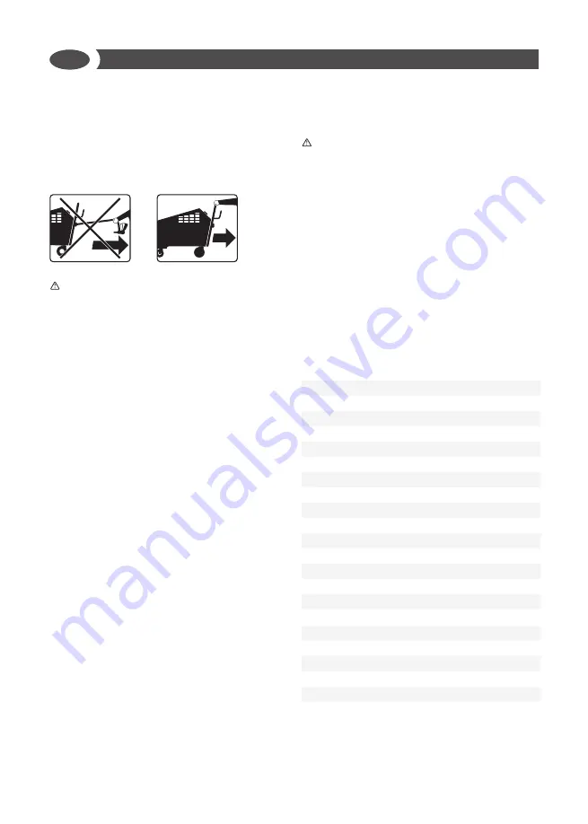
To move the machine inside the industrial area,
always use the special handle; never use the power
supply cable or the gun cable to move it.
WARNINGS
- Only use a forklift truck or a crane to lift the
machine, since it is not perfectly balanced.
- Lift the machine only by means of steel
cables or bands duly dimensioned
according to the machine weight.
- Lift the machine by means of the safety
hooks.
- No foreign operator must stay or pass in
the handling area while the operators
responsible for the machine transport will
have to keep at a suitable distance to avoid
being intercepted by the machine.
- Never make sudden manoeuvres while
lifting and handling the machine so that
it cannot intercept any people or object
present in the handling area.
- An operator staying outside the handling
area will have to follow all the handling
activities and signal any possible obstacle
the crane operator cannot see.
- In case of sea transport, it is advisable
to protect the various machine parts by
covering them with antirust lubricating
agents and to add some bags containing
hygroscopic salts to the packaging.
- Once positioned on the truck (or any
transport mean) the machine must be
braced by ropes, steel cables or wooden
wedged duly dimensioned according to the
machine weight.
MACHINE INSTALLATION
WARNINGS
- The machine must be installed in a place where
the best hygrothermometrical conditions
are observed for the safety of the operator in
order to reduce the possibility of fatigue to the
minimum and to allow the operator to work in
the maximum safety conditions.
- The machine installation area will have to be
well-ventilated and free from explosive gases.
- The temperature of the machine installation
area will have to range between 10°C and 35°C.
View with the machine main references
fig. pag. 2
DESCRIPTION OF THE MACHINE
①
Main switch ON/OFF
②
LINE orange pilot light
③
Thermoregulator
③+ ③-
④
Display
⑤
BOILER START push-button:
⑥
GUN START push-button:
⑦
Detergent adjustment
⑧
Steam adjustment
⑨
Pressure gauge
⑩
Control panel
⑪
Gun connection plug
⑫
Steam gun
⑬
Boiler drain tap
⑭
Water tank
⑮
Detergent tank
⑯
Water inlet
⑰
Water inlet filter
⑱
Steam supply lever (gun)
⑲
Detergent spray switch (gun)
⑳
Gun connection plug/ socket
㉑
Water tank drain plug
EN
20
Summary of Contents for 9204 0006
Page 2: ...2...
Page 16: ...16...
Page 28: ...EN 28...
Page 76: ...SL 76...
Page 78: ...OFF 09c 60 16c 17c 17c IEC OFF L RU 78...
Page 79: ...60364 1 30 A 30 04i 23i 21i 08i 22i 10 180 RU 79...
Page 80: ...10 35 RU 80...
Page 81: ...2 ON OFF elettriciy BOILER START GUN START k 1000 400 RU 81...
Page 83: ...2 ON OFF H2O IL R START GUN START GUNSTART OFF RU 83...
Page 85: ...OFF A 1 2 RU 85...
Page 86: ...3 4 5 6 7 8 9 2012 19 EU 2012 19 EU RU 86...
Page 87: ...RU 87...


