33
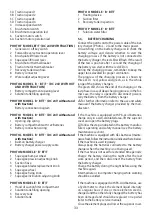
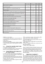
3A Traction speed 1
3B Traction speed 2
3C Traction speed3
3D Traction speed 4
4 Increase speed switch
5 Brush motor switch
5A Brush motor operation led
6 Suction motor switch
6A Suction motor operation led
PHOTO F MODEL BT/T - (DC 24V WITH TRACTION)
1 General on / off key switch
2 Forward/reverse traction operation lever
3 Brush plate lift/lower lever
4 Squeegee lift/lower lever
5 Brush motor thermal breaker
6 Traction motor thermal breaker
7 Recovery tank drain hose
8 Battery connector
9 Water outlet adjusting lever
PHOTO G MODEL B - BT/T - (DC 24V WITHOUT
AND WITH TRACTION)
1 Battery compartment opening lever
2 Solution tank filling opening
PHOTO H MODEL B - BT/T - (DC 24V without and
with traction)
Battery connection diagram
PHOTO I MODEL B - BT/T - (DC 24V without and
with traction)
1 Opening clip spring
2 Battery compartment with 12v Batteries
3 Battery connection wiring
PHOTO L MODEL B - BT/T - (DC 24V without and
with traction)
1 Built-on battery charger
2 Battery charger power supply cable
PHOTO M MODEL E - B - BT/T
1 Squeegee bumper wheel
2 Squeegee pression adjusting knob
3 Suction hose
4 Squeegee blades replacement knob
5 Squeegee wheel
6 Squeegee fixing knob
7 Squeegee inclination adjusting knob
PHOTO N MODEL E - B - BT/T
1 Hood of suction filter compartment
2 Solution tank filling opening
3 Recovery tank
4 Solution tank
PHOTO O MODEL E - B - BT/T
1 Floating device
2 Suction filter
3 Recovery tank inspection
PHOTO P MODEL E - B - BT/T
1 Solution water filter
5.3.
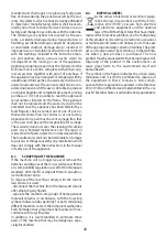
BATTERY CHARGING
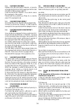
Connect the patch cord to the power cable of the bat-
tery charger ( Photo L - 2 ) and to the mains power.
On switching on the battery charger will check the
battery voltage and decide whether to start the
charging process. If the battery is not connected to
the battery charger, the red LED will flash. If the result
of the test is positive after 1 second the charging of
the battery can start, with the red LED on.
During the charging process, remember to keep the
upper tank elevated for proper ventilation.
The progress of the charging process is shown by
three LED’s: red, yellow and green, as in the whole
range of the battery chargers.
The green LED shows the end of the charging or the
last phase in case of deep charging process; in the for-
mer case, the relay is opened to disconnect galvani-
cally the battery from the battery charger.
•
For further information refer to the use and safety
manual of the battery charger provided by the man-
ufacturer.
If the machine is equipped with Pb-Acid batteries,
charge only in a well-ventilated area, lift the superior
cover and open the battery plugs.
•
Follow the steps indicated in the battery manufac-
turer’s operating and safety manual (see the battery
maintenance section).
If the machine is equipped with GEL batteries (mainte-
nance free), follow the instructions indicated here below.
If the machine is used regularly:
Always keep the batteries connected to the battery
charger when the machine is not being used.
If the machine is not used for extended time periods:
Charge the battery during the night after the last
work period, and then disconnect the battery from
the battery charger.
Charge the battery during the night before using the
machine again.
Intermediate or incomplete charging while working
should be avoided.
If the machine is equipped with Pb-Acid batteries, use
a hydrometer to check the element liquid intensity
on a regular basis: if one or more elements are dis-
charged and the others fully charged, the battery has
been damaged and should be replaced or repaired
(refer to the battery service manual).
Close the element plugs and lower the superior cover.
Summary of Contents for CPS 50 B
Page 3: ...3 2 1 3 A B 6 1 3 4 5 2 E AC 230V...
Page 4: ...4 C D 2 2A 3A 3B 3C 1A 1 3 6 3 4 5 1 8 2 B DC 24V 7...
Page 6: ...6 H G 1 2 1 3 2 I...
Page 7: ...7 1 2 L M 1 1 4 4 3 2 5 7 6 5 2 6...
Page 8: ...8 N O 1 1 2 3 3 2 4...
Page 9: ...9 P 1...
Page 91: ...91 1 1 1 1 2 2 10 1 3 1 4...
Page 92: ...92 1 5 2 2 1 4 35 10 50 30 95 2 10...
Page 93: ...93 2 2...
Page 94: ...94 3 3 1 3 2 3 3 C C 3 4...
Page 95: ...95 4 4 1 20 20 20h 5 5 5h 5 5 20 20 24 4 1 1 4 1 2 I 2 G 1 3 I 1 I 2...
Page 101: ...101 2 2 2 P 1 5 11 3 1 5 D 6 F 7 3 5 12 AC 230V AC230 AC 230V...
Page 103: ...103 5 14 5 14 1 5 14 2 3 1 3 1 5 14 3 6 13 5 14 4 6 13 6 14 3 5 14 5 6 11 6 6 1 50...
Page 104: ...104 6 2 M 3 6 3 6 4 6 5 6 6 6 7...
Page 105: ...105 6 8 6 8 1 6 8 2 6 8 3 6 9 7 7 1 1 C 7 2 5 7 3...
Page 106: ...106 7 4 7 5 7 6 7 7 7 8 7 9 7 10 100 20 30 8 12...
Page 107: ...107 8 1 2013 56 EU 8 2 2012 19 EU 2012 19 EU...
Page 124: ...124...
Page 125: ...125...
Page 126: ...126...
Page 127: ...127...
Page 128: ...128...
Page 129: ...129...
Page 130: ...130...
Page 131: ...131...
Page 238: ...238 1 1 1 1 2 2 10 1 3 a 1 4...
Page 239: ...239 1 5 2 2 1 4 C 35 C 10 C 50 C 30 95 2 10...
Page 240: ...240 2 2 3 3 1 3 2 3 3...
Page 241: ...241 3 4 4 4 1 Ah 20 C20 20h 5 C5 5h C5 C20...
Page 247: ...247 50 C N 4 N 3 2 N 2 2 L Q 1 5 11 N 3 0 1 B 6 D 6 F 7 0 3 5 12 230V 230V AC 230V...
Page 249: ...249 5 14 2 C 3 E 1 C 3C E 1C 5 14 3 6 13 5 14 4 6 13 6 14 3 5 14 5 6 11 6 6 1 50 6 2 3...
Page 250: ...6 3 250 6 4 6 5 X X X X X X X X X X X X X X X X X X...
Page 251: ...251 6 6 BPb 3 AGM 6 6 7 6 8 6 9 7 7 1 ON 7 2 5 7 3...
Page 252: ...252 7 4 7 5 7 6 7 7 7 8 7 9 7 10 100 20 30 8 12...
Page 253: ...253 8 1 2013 56 8 2 WEEE 2012 19 2012 19 EU...
Page 255: ...255 1 1 1 1 2 2 2 10 1 3 1 4...
Page 256: ...256 1 5 2 2 1 4 C 35 C 10 C 50 C 30 95 2 10...
Page 257: ...257 2 2 134 3 3 1 3 2 3 3...
Page 258: ...258 3 4 4 4 1 4 1 1 Ah 20 C20 20h 5 C5 5h C5 C20...
Page 263: ...263 5 4 M 6 6 M 3 5 5 M 6 5 6 6 5 M 4 M 6 M 4 M 6 6 4 5 7 7 2 45 M 2 M 7 5 8 5 9 1 cm 1 cm...
Page 264: ...264 5 10 50 C N 4 N 3 G 2 N 2 2 cm 5 11 N 3 1 B 6 D 6 F 7 3 5 12 E AC 230V E AC 230V...
Page 267: ...6 2 M 3 6 3 267 X X X X X X X X X X X X X X X X X X...
Page 268: ...268 6 4 6 5 6 6 3 AGM 6 6 7 6 8 6 9 7 7 1 7 1 1 1...
Page 269: ...269 30 7 1 2 5 7 1 3 7 1 4 7 1 5 7 1 6...
Page 270: ...270 7 1 7 7 1 8 7 1 9 7 1 10 100 20 30 8 12 8 1...
Page 271: ...271 2013 56 E 8 2 2012 19 2012 19...

