background image


14


IE-SNC-T83(4)48-03


Troubleshooting 


Error states of the device 

 
Device  continuously  checks  its  state  during  operation.  In  case  error  is 
found LCD displays corresponding error code: 

Error 0 

-  

first line displays „Err0“. Check sum error of stored setting inside 
device’s  memory.  This  error  appears  if  incorrect  writing 
procedure  to  device’s  memory  occurred  or  if  damage  of 
calibration data appeared. At this state device does not measure. 
It is a serious error, contact distributor of the device to fix. 

Error 1 

-  t

here is a reading „Err1“ on LCD display. Measured temperature 

is over upper limit of allowed full scale range. This state appears 
in  case  of  measured  temperature  is  higher  than  approximately 
600°C  (i.e.  high  non-measurable  resistance  of  temperature 
sensor, probably opened circuit). 

Error 2 

-  t

here is a reading „Err2“ on LCD display. Measured temperature 

is  below  lower  limit  of  allowed  full  scale  range  or  CO

2


concentration measurement error occurred. Value read from the 
device  is  -999.9..  This  state  appears  in  case  of  measured 
temperature  is  lower  than  approximately  -

210°C  (i.e.  low 

resistance of temperature sensor, probably short circuit). 

Error 3 

-  t

here  is  a  reading  „Err3“  on  LCD  display  upper  line.  Error  of 

internal  A/D  converter  appeared  (converter  does  not  respond, 
probably damage of A/D converter). At this state device does not 
measure  temperature.  This  error  does  not  affect  CO

concentration  measurement.  It  is  a  serious  error,  contact 
distributor of the device. 

Error 4 

there is a reading „Err4“ on LCD display. It is internal device error 
during  CO

2

  concentration  sensor  initialization.  Under  this 

condition  device  does  not  measure  concentration  of  CO

2

.  Value 

read from device is -999. It is a serious error, contact distributor 
of the device


Technical support and service 


Technical  support  and  service  is  provided  by  distributor.  For  contact  see 
warranty  certificate.You  can  use  discussion  forum  at  web  address 

www.forum.cometsystem.cz

Summary of Contents for T8348

Page 1: ... Instruction Manual T8348 programmable indoor transmitter of temperature and CO2 concentration with RS232 serial output T8448 programmable indoor transmitter of temperature and CO2 concentration with RS485 serial output ...

Page 2: ...rovement of their products Manufacturer reserves the right to make technical changes to the device without previous notice Misprints reserved Manufacturer is not responsible for damages caused by using the device in conflict with this manual To damages caused by using the device in conflict with this manual can not be provide free repairs during the warranty period Read carefully instruction manua...

Page 3: ...TOCOLS 10 MODBUS RTU 10 PROTOCOL COMPATIBLE WITH ADVANTECH ADAM STANDARD 12 ARION COMMUNICATION PROTOCOL AMIT COMPANY 13 TROUBLESHOOTING 14 ERROR STATES OF THE DEVICE 14 TECHNICAL SUPPORT AND SERVICE 14 TECHNICAL DATA 15 MEASURED VALUES 15 GENERAL SPECIFICATIONS 15 OPERATING CONDITIONS 16 END OF OPERATION 16 DIMENSIONS 17 TYPICAL APPLICATION WIRING 17 APPENDIX A 18 ...

Page 4: ...ause the control would trigger a change of the ventilation based on this one time measurement On the contrary in FAST mode no software filter is used for calculating the output value This fact adds a noise of typ 30ppm which has to be considered in terms of accuracy The measured value of CO2 concentration depends on the value of air pressure the altitude at the place of installation For this reaso...

Page 5: ...n manual pdf which is installed commonly with the software Change of some parameters is possible to do without user s software with Windows hyperterminal change of communication protocol its parameters LCD display setting It is described in file Description of communication protocols free to download at www cometsystem cz Models marked TxxxxZ are non standard versions of the transmitters Descripti...

Page 6: ...device address 1 communication speed 9600Bd without parity 2 stop bits display switched ON value displayed at higher line CO2 concentration value displayed at lower line temperature temperature unit C measurement CO2 mode SLOW LED indication up to 1000 ppm lights green LED between 1000 and 1200 ppm lights yellow LED and over 1200 ppm lights red LED altitude 300 m above see level at the installatio...

Page 7: ...able screwdriver for the opening insert the screwdriver to upper terminal hole and lever by him Nominal cable impedance should be 100 Ω loop resistance max 240 Ω cable capacity max 65 pF m Suitable cable is e g SYKFY 2x2x0 5 mm2 where one wire pair serves for device powering and the other pair for communication link The cable should be led in one line i e not to tree or star Termination resistor s...

Page 8: ... insert screwdriver beyond the fastening member about 2 cm deep Then slightly move screwdriver in arrow direction it unlock fastening member and the device is partially opened Remove the screwdriver and take front part of device at top Pull front part with pendulum motion and remove front cover If there is necessary remove rear part of the device please disconnect cables and unscrew two holding sc...

Page 9: ... same side as button Shortly press button behind small hole on the left side of the device using thin instrument for example paper clip Actual adjusted address of the device is displayed on LCD display at decimal base Next press of button exits info mode and actual measured values are displayed Devices with RS232 interface have address always set to one No measurement and communication is possible...

Page 10: ...r proceeds in binary format Each Byte is sent as eight bit data word in format 1 start bit data word 8 bit LSB first 2 stop bits device sends two stop bits for receive one stop bit is enough without parity Device supports communication speed from 110Bd to 115200Bd Sent request and response have syntax ADDRESS OF DEVICE FUNCTION Modbus CRC Supported function 03 0x03 Reading of 16 bit registers Read...

Page 11: ...unication protocol is done Modbus registry snímače Variable Unit Address hex X Address dec X Format Size Status Measured temperature C F 0x0031 49 Int 10 BIN16 R CO2 concentration displayed on LCD ppm 0x0034 52 Int BIN16 R CO2 concentration FAST mode ppm 0x0054 84 Int BIN16 R CO2 concentration SLOW mode ppm 0x0055 85 Int BIN16 R Serial number of device Hi 0x1035 4149 BCD BIN16 R Serial number of d...

Page 12: ...is transferred in ASCII format in characters Each Byte is sent as two ASCII characters Device supports communication speed from 1200Bd to 115200Bd parameters of communication link are 1 start bit eight bit data word LSB first 1 stop bit without parity Jumper Jumper is located next to connection terminals If communication protocol compatible with standard Advantech ADAM is selected its function is ...

Page 13: ... more than one value there is necessary to add at the end of command the number of communication channel where the measured value is mapped Command for value reading is AAx CRC cr where AA is device address x is number of communication channel CRC is check sum can be used or not Measured value Number of communication channel Temperature 0 CO2 concentration 3 Command AA CRC cr for reading all measu...

Page 14: ...r limit of allowed full scale range or CO2 concentration measurement error occurred Value read from the device is 999 9 This state appears in case of measured temperature is lower than approximately 210 C i e low resistance of temperature sensor probably short circuit Error 3 there is a reading Err3 on LCD display upper line Error of internal A D converter appeared converter does not respond proba...

Page 15: ...rement mode t90 75 s in FAST measurement mode Temperature Accuracy 0 5 C 0 9 ºF Measuring range 10 to 50 C 14 to 122 F Resolution 0 1 C Response time t90 6 min air flow approximately 0 3 m s t90 11 min no air flow General specifications RS485 interface Receiver Input Resistance 96 kΩ Devices on bus max 256 1 8 Unit Receiver Load Power supply voltage 9 to 30 Vdc Power consumption 0 5 W during norma...

Page 16: ... 95 RH no condensation Storage pressure range 700 to 1100 hPa Electromagnetic compability EN 61326 1 Weight approximately 150 g Housing material ABS Operating conditions Operating temperature range 10 to 50 C 14 to 122 ºF Operating relative humidity range 5 to 95 RV no condensation Operating pressure range 850 to 1100 hPa End of operation Dispose of the device according to statutory regulations ...

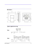
Page 17: ...IE SNC T83 4 48 03 17 Dimensions Typical application wiring T8348 T8448 ...

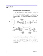
Page 18: ...e corresponding pins of CANON connector for more information see the operation manual for ELO E214 The ELO E06D converter is an optional accessory for connection of transmitter with RS485 interface to the PC via serial port RS232 Connector marked RS232 connect directly to the PC Power voltage 6V DC from an external acdc adapter connect to pin 9 of connector marked RS485 0V connect to pin 5 and lin...

Reviews: