background image

©COMEV

AL

 V

AL

VE SYSTEMS 

Technical Dept. Ref. IOM - PNEUMA

TIC 

ACTUA

TORS 

AF SERIES - Ed.20/1

Comeval V

alve Systems reserves the right to alter any technical data contained in this Manual without prior notice. Regularly updated data on www

.comeval.es

COLUMNLESS PNEUMATIC ACTUATORS AF SERIES 

FOR DIAPHRAGM VALVES

Page 3

4.2

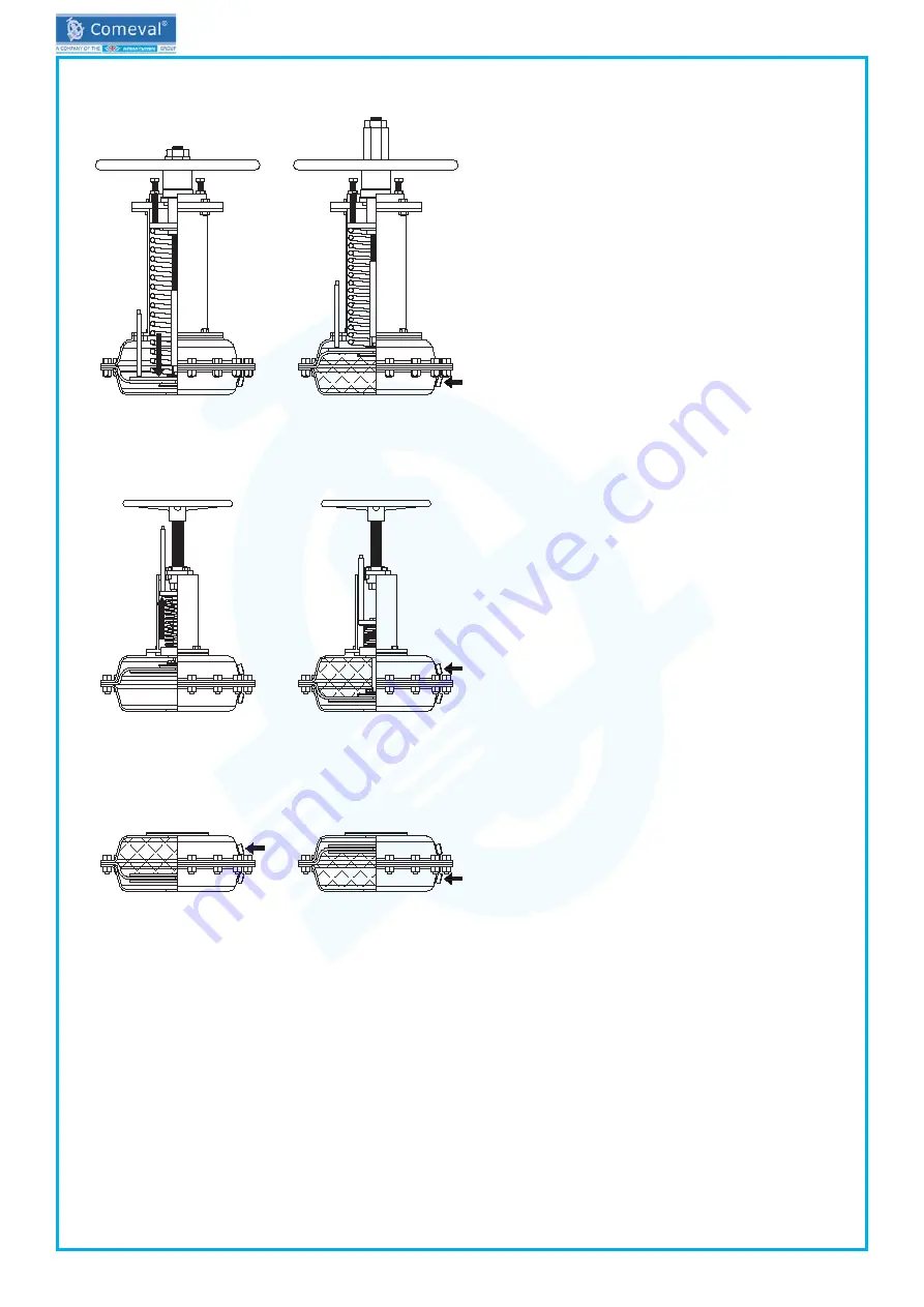
  Principle of Operation

Single acting, spring return, normally closed actuator

air inlet

When the lower chamber is pressureless the spring forces the valve’s stem down to close. If the lower chamber has enough 

air pressure to counter the spring’s force (based on limit rod screws set up) and the pipeline diferential pressure, the diaphragm 

upper plate pushes up the spring and therefore the valve opens.

Single acting, spring return, normally closed actuator

air inlet

When the upper chamber is pressureless the spring forces the valve to remain open, the % on the opening could be easily 

adjusted by using the handwheel which actuate directly to the stem extension. When the upper chamber have enough air 

pressure to counter the pressure of the line and the spring’s force, the air push the diaphragm downwards and this pull the 

stem extension with it forcing the valve to close.

Double acting

air inlet

air inlet

When the upper chamber’s air pressure is enough to allow the valve to close, the air pushes the diaphragm downwards and 

so it actuates directly on the valve’s stem forcing the valve to close. When the air pressure in the lower chamber is enough to 

allow the valve to open, the diaphragm push upwards the stem and so the valve open.

4.3

  Area of Application

Diaval® AF actuators have been designed to automatize diaphragm valves installed on pipelines for liquids or gases suitable 

for the valves.

4.4

  Technical data – remarks

Check installation area’s special requirements, air supply and temperature limits and other essential parameters. Ensure 

proper safety devices/measures are implemented to prevent exceeding intended use of the product. Refer to Data Sheet for 

data such as main features, duties/limits of use, dimensions, weights, etc. and consult the manufacturer for further information. 

Bear in mind that for the correct operation, a pneumatic actuator must be sized adequately and with sufficient safety margin 

of thrust output for the correct operating conditions of the valve.

Spring return actuators are equiped with visual indicator rod.

Summary of Contents for Diaval AF Series

Page 1: ... on safety information 2 3 PRESERVATION STORAGE HANDLING TRANSPORT 2 4 DESCRIPTION 2 4 1 General Description Operating principles 2 4 2 Principle of Operation 3 4 3 Area of Application 3 4 4 Technical data remarks 3 4 5 Marking labelling 4 5 INSTALLATION 4 5 1 General remarks on installation 4 5 2 Assembly of the actuator onto de valve 4 5 3 Assembling additional modules 4 5 4 Requirements at the ...

Page 2: ... observed and complied with for safely using the product 3 PRESERVATION STORAGE HANDLING TRANSPORT ATTENTION Protect against external force impacts vibrations etc Allow only skilled personnel suitable handling and lifting equipment must be used See Data Sheet for weights or consult manufacturer Always use suitable protection equipment and minimize the use of human body force at any step to avoid i...

Page 3: ...ce the air push the diaphragm downwards and this pull the stem extension with it forcing the valve to close Double acting air inlet air inlet When the upper chamber s air pressure is enough to allow the valve to close the air pushes the diaphragm downwards and so it actuates directly on the valve s stem forcing the valve to close When the air pressure in the lower chamber is enough to allow the va...

Page 4: ...nd in rest position installed on the pipe line When the valve is operated there is a crushing hazard between diaphragm and seat Ensure the valve is not under operation in case hands are introduced inside the valve To avoid unnecessary stress and risk of valve break consider the weight and the relative position of actuator to evaluate its support Make sure that the actuator is suitable for service ...

Page 5: ...ly as well as actuator controls and valve 7 CARE AND MAINTENANCE The operator must define maintenance and maintenance intervals to meet requirements Check for body and air supply connections tightness and valve smooth operation without additional tools ATTENTION Before any maintenance task make sure previous chapters are thoroughly followed In case of actuator malfunction and cap screws loosened t...

Page 6: ...ove the between chambers bolts 9 Remove the upper chamber 10 Remove the retaining washers and the stem extension 11 Remove the diaphragm upper plate the diaphragm and the bottom suport plate 12 Remove the bonnet 13 Clean the components of the actuator perfectly 14 Inspect the components of the actuator for wear or damage and replace what is necessary Normally open actuator assembly after maintenan...

Page 7: ...ing and replace if needed Refer to chapter 7 Some part stuck inside the valve Dismount the valve and check inside Refer to chapter 7 Actuator unit moves too slowly or not reaching limit position Air supply pressure too low Recheck air supply pressure on actuator nameplate Increase only the needful without exceeding max value Connection opposite to air supply connection partially plugged or restric...

Page 8: ...ially polluting or harmful residues or any mechanical damage that could present a health safety or environmental risk as enforced by EU Health Safety and Environment Law including the Safety Data Sheet of the substances identified as potentially hazardous Actuators are recyclable and not expected hazard to the environment with the exception of soft parts PTFE and rubber compounds that should be di...

Page 9: ...10 11 16 14 15 22 13 1 2 3 4 5 6 7 8 9 10 11 12 13 14 15 16 20 Single Acting spring to open 1 5 9 18 6 8 2 13 16 14 15 22 11 10 7 No Description 1 Handwheel 2 Stem extension 3 Nut 4 Opening limit rod 5 Spring chamber bolts 6 Spring plate 7 Spring chamber 8 Spring 9 Visual indicator 10 Upper chamber 11 Chambers union bolts 12 Retainer bolt 13 Retainer washers 14 Diaphragm upper plate 15 Diaphragm 1...

Page 10: ...DIAPHRAGM VALVES Page 10 Double Acting 16 14 15 14 19 10 11 10 11 19 14 15 16 No Description 10 Upper chamber 11 Chambers union bolts 14 Diaphragm upper plate 15 Diaphragm 16 Lower chamber 19 Stem s locking nut 14 ANNEXES 14 1 Declaration of Conformity DC09 14 2 Data Sheet DS09 COMEVAL VALVE SYSTEMS S L y CIA Soc Comanditaria Les Rotes 15 46540 El Puig Valencia España Phone 34 961 479 011 Fax 34 9...

Reviews: