7
3.3.
Connecting the power supply and receivers
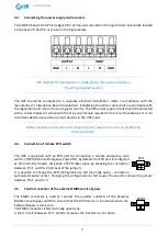
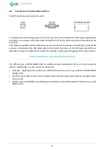
The CORE 6K and 10K UPS is designed for permanent connection through the terminal block located
on the back of the UPS, as shown in the figure below.
OUTPUT
INPUT
GND
L
N
L
N
GND
UPS adapted for installation in a single-phase, three-wire installation,
TN with a grounded neutral.
The UPS should be connected to a separate electrical installation, made in accordance with the
manufacturer's Installation Recommendations. Installation should be carried out in accordance with
the regulations and rules in force in a given country. The UPS power supply circuit should be protected
with a circuit breaker or a fuse with the trip current value required in the recommendations. It is not
recommended to use residual current devices in the UPS input.
Cables should be connected and arranged in such a way that no one can accidentally
disconnect them.
3.4.
Connection of remote EPO switch
The UPS is equipped with an EPO port for connecting a remote emergency stop
switch. / REPO (Remote Emergency Power Off). By default, the EPO port is configured
as NC (normally closed), activation of EPO takes place by breaking the connection
between Pin 1 and Pin 2 (removal of the jumper).
It is possible to change the EPO configuration to NO (normally open) - contact an
authorized service center. Changing the configuration to NO causes the need to remove the jumper
between Pin 1 and Pin 2.
3.5.
Control connector of the external EMBS service bypass
The EMBS connector is used to connect the auxiliary contacts of the External
Maintenance Bypass switch to ensure that the UPS inverter is shut down when the
External Bypass is turned on.
The EMBS connector is NO (normally open) type.
A short circuit (between Pin 1 and Pin 2) causes the inverter to shut down.
EPO
EMBS


