background image

COVER MY SERIES  – User Manual


COMEX S.A.


25 


4.3.


Procedures for switching the power supply between operating modes 

4.3.1.


Switching from normal operation to battery mode  

Open the rectifier power disconnect switch to disconnect the UPS power. The UPS will go into 
battery operation. If the power supply is to be reconnected to normal operation, wait a few 
seconds  and  then  close  the  charger  supply  disconnect.  After  about  10  seconds,  the  rectifier 
starts up and enters the normal operation mode. 

4.3.2.


Switching from normal operation to bypass operation 

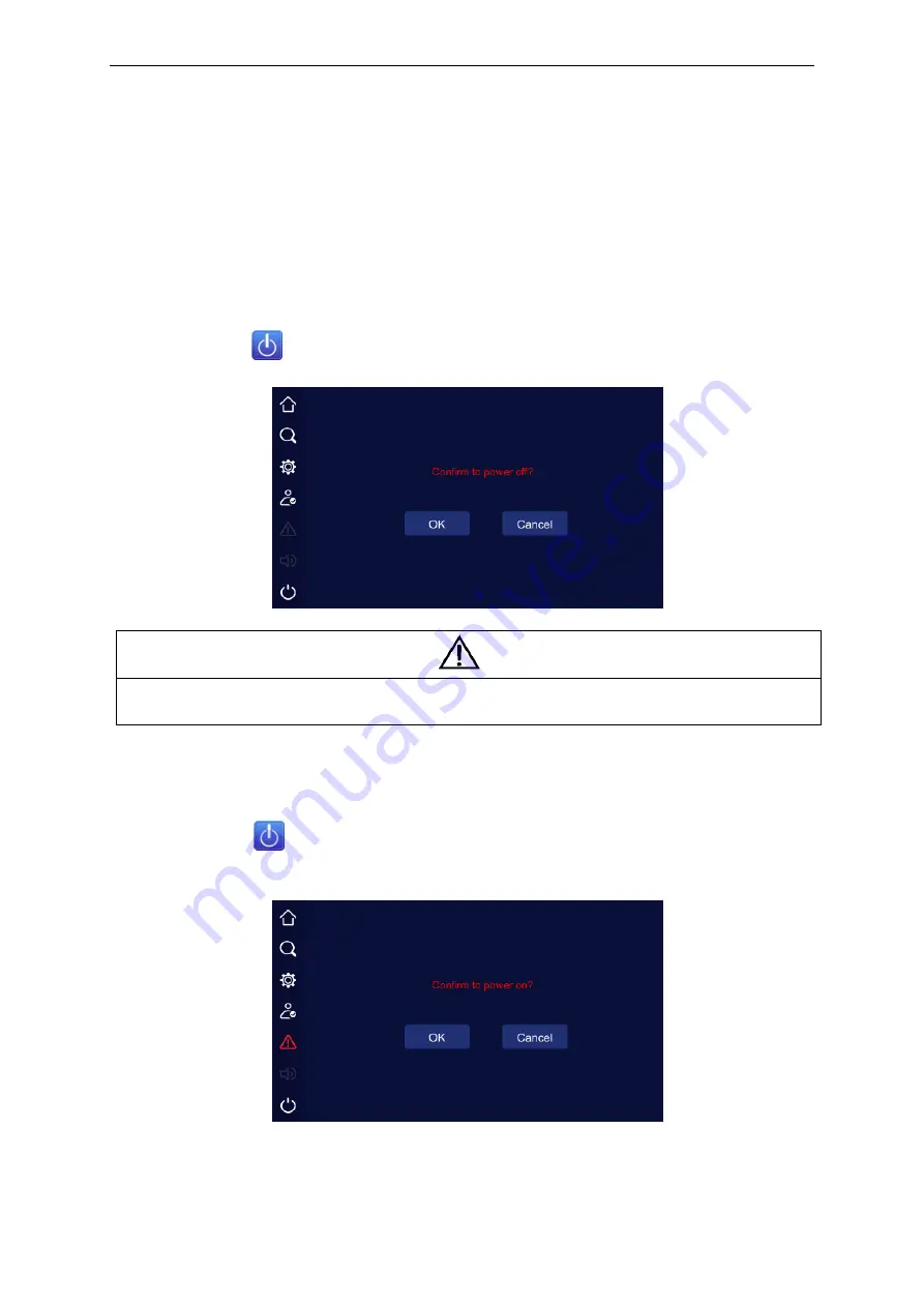
Press the icon key 

 on the LCD panel, and then Confirm shutdown with OK. 


Warning 

In the Bypass mode, the loads are supplied directly from the mains and are not protected 
against the effects of blackouts and disturbances in the mains. 


4.3.3.


Switching from Bypass to normal operation 

Press the icon key 

 on the LCD panel, and then confirm that the inverter is turned on with 

the OK key. The UPS will transfer from Bypass Mode to On-Line Mode. 


警告


危 险


Summary of Contents for COVER MY 30k

Page 1: ...COMEX S A Uninterraptible power supply UPS COVER MY 30 kVA kW User Manual...

Page 2: ...his document is the copyright of the publisher and may not be reproduced without prior permission The right to modify the design and specifications is reserved without prior notice Copyright 2020 COME...

Page 3: ...ommunication 14 2 7 1 Dry Contact IN OUT communicationomun 14 2 7 2 Parallel connection 17 2 7 3 Communication card slots 17 2 7 4 Modbus RTU RS485 connector 18 3 UPS operation modes 19 3 1 Introducti...

Page 4: ...8 5 1 Introduction 28 5 2 Indications of the UPS operating status on the display 29 5 3 Reading the operating parameters 30 5 3 1 Power supply of the bypass line 30 5 3 2 Rectifier track supply 31 5 3...

Page 5: ...ing battery Earthing should be performed in accordance with the prevailing standards and practical knowledge in the place of installation The leakage current is greater than 3 5mA and less than 1000mA...

Page 6: ...across their terminals exceeds 400 Vdc and is potentially lethal Battery manufacturers provide detailed precautions that must be observed when working on or in the vicinity of large battery batteries...

Page 7: ...sequence is not covered by the warranty Warning Dangerous Batteries Particular precautions must be taken when working with batteries connected to the power supply When the battery is connected the te...

Page 8: ...mperatures reduces their capacity Each increase of the battery operating temperature by another 8 C reduces the service life by 50 Keep batteries away from heat sources and hot air vents When installi...

Page 9: ...wer etc Note The protective materials remaining after dismantling wood plastic etc must be disposed of in accordance with the applicable local environmental regulations In order to extend the life of...

Page 10: ...ual COMEX S A 6 2 4 2 The appearance and dimensions of the UPS The appearance and dimensions mm of the UPS are shown in the figures below Figure 2 2 Front side view of the MY 30K UPS Figure 2 3 Bottom...

Page 11: ...ossibility of drawing cold air from the environment Recommended space from the front 80 cm Due to the required access to the rear of the power supply as well as free air exhaust and circulation the re...

Page 12: ...equired with a center neutral point taken from the central connection between battery 20 and 21 in the case of a string 40 of batteries The battery circuit must be protected with an appropriate fuse s...

Page 13: ...t the rated power of the PSU The terminal block for connecting the power receiving cables in the 30kVA UPS is located on the back of the UPS The strip has M6 bolt and eyelet connections Cable access i...

Page 14: ...ng The operations described in this section should be performed by a properly trained service team The ordering party is responsible for the preparation of the power supply and receiving installation...

Page 15: ...ting in 3 3 configuration two line power supply on the left or single line power supply on the right In the case of the configuration of the power supply to the 3 1 mode switch the wiring of the opera...

Page 16: ...lations and applicable standards 5 Connect the UPS rectifier and bypass power supply and the receiving cables Warning Dangerous voltage at the battery terminals 6 Install the protective cover and the...

Page 17: ...reaker 2 N Figure 2 12 Diagram of connection of external batteries for a single chain NO 1 Battery cabinet 1 NO 2 NO 16 NO 3 NO 17 NO 18 NO 32 NO 19 NO 1 Battery cabinet 2 NO 2 NO 16 NO 3 NO 17 NO 18...

Page 18: ...potential free connectors 1 and 3 a parallel operation connector 2 optional two communication card slots 6 and 7 optional and a communication connector Modbus RTU RS485 5 There is also a USB port behi...

Page 19: ...g Battery error or battery parameters incorrect NO COM OUT 4 NC Default setting Output error NO COM OUT 5 NC Default setting Output overload NO COM Dry contact 2 EPO EPO uses the NC connection The EME...

Page 20: ...Description 1 No Supply The occurrence of the event occurs when the primary rectifier power supply fails or when the power supply parameters are outside the tolerance range 2 No bypass The occurrence...

Page 21: ...tem or increase the system reliability In order to be able to connect UPSs in parallel operation each UPS must be equipped with parallel operation cards and the cables between them enabling mutual com...

Page 22: ...re sensor and battery disconnect status also configurable as remote UPS On Off status detection RS232 RS485 Slot 1 2 The card is equipped with a DB 9 port for communication via RS232 or RS485 serial p...

Page 23: ...arantees high frequency double processing with pulse width modulation PWM all controlled using digital signal processing DSP which ensures high reliability and convenience of use 3 2 Principle of oper...

Page 24: ...the UPS operates in the electronic bypass mode Warning When the UPS operates in the Bypass or Maintenance Bypass mode the connected receivers are not protected against power outages and mains disturba...

Page 25: ...ped with allows for periodic maintenance work on the device without de energizing the loads connected to the UPS The service bypass can be activated only when the UPS operates in the electronic bypass...

Page 26: ...ices in parallel which means that the maximum power of a system based on e g MY30K UPS is 240kVA In parallel operation of the UPS units the load is evenly distributed among all operating UPS units In...

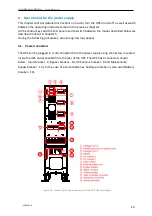
Page 27: ...bed in detail in Chapter 5 During the following procedures acoustic signals may appear 4 1 Power connectors The UPS can be plugged in or disconnected from the power supply using connectors mounted ins...

Page 28: ...On buttons on the display panel or by using commands from the display panel To start the UPS with the ON buttons press and hold both ON buttons simultaneously for three seconds The UPS will start the...

Page 29: ...y disconnect After about 10 seconds the rectifier starts up and enters the normal operation mode 4 3 2 Switching from normal operation to bypass operation Press the icon key on the LCD panel and then...

Page 30: ...discharge 4 3 5 Switching from the Service Bypass mode to normal operation The procedure described below allows the UPS to transfer from Bypass to Normal operation 1 Close the Output breaker and the i...

Page 31: ...d automatically and the panels will be turned on The UPSs operate in bypass mode 3 If the UPS displays do not show any system malfunction turn on the battery disconnect switch located near the battery...

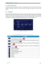
Page 32: ...rameters and event recording Below is presented the main page of the display and the meaning of particular icons that may appear on it Figure 5 1 Touch display Table 5 1 Description of symbols used on...

Page 33: ...S can operate such as starting shutdown parallel system output mechanical bypass operation bypass operation battery operation normal operation aging mode ECO mode frequency converter mode protection a...

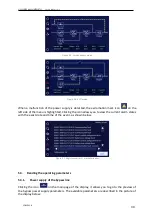
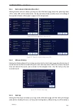
Page 34: ...e icon allows you to view the current alarm states with the exact date and time of the event as shown below Figure 5 1 Registered errors crashes window 5 3 Reading the operating parameters 5 3 1 Power...

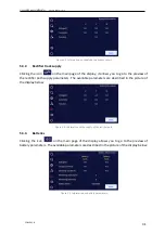
Page 35: ...the rectifier path supply parameters The available parameters are described in the picture of the display below Figure 5 9 Information on the supply of the rectifier path 5 3 3 Batteries Clicking the...

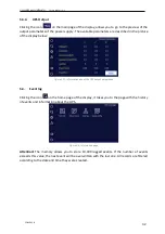
Page 36: ...igure 5 11 Information about the UPS output parameters 5 4 Event log Clicking the icon on the home page of the display it takes you to the page with the history of events and information about the UPS...

Page 37: ...a Run Info Paralle operation UPS 5 4 2 UPS event history Clicking the History Record icon allows you to go to the information page about the history of events and alarms that occurred in the past or a...

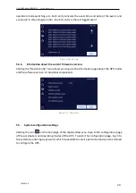
Page 38: ...the Device config Icon allows you to go to the information page about the UPS model and the software version of individual components Figure 5 17 Device info 5 5 System configuration settings Clicking...

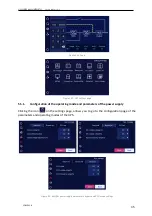
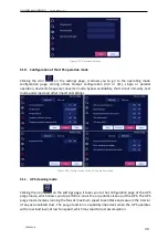
Page 39: ...age 5 5 1 Configuration of the operating mode and parameters of the power supply Clicking the icon on the settings page allows you to go to the configuration page of the parameters and operating modes...

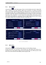
Page 40: ...onnected from the charger may be up to 30 days depending on the configuration In order to protect the batteries against overcharging there is also a function of temperature compensation of the chargin...

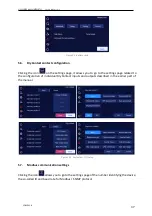
Page 41: ...go to the settings page related to the configuration of individual DryContact inputs and outputs described in the earlier part of the manual Figure 5 23 DryContact I O setup 5 7 Modbus communication...

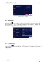
Page 42: ...ou to go to the settings page related to the current system date language and display contrast UPS has seven built in languages incl Polish English Italian Spanish Russian Chinese Korean Figure 5 25 D...

Page 43: ...nity test mode under load and other important settings Figure 5 28 Configuration of the UPS operation mode 5 11 UPS cleaning mode Clicking the icon on the settings page it takes you to the configurati...

Page 44: ...ions and UPS alarms and cleaning the runtime of fans and condensers Clicking on the floppy disk icon saves the history in the device s USB memory available for the service Figure 5 30 History record 5...

Page 45: ...con After silencing the alarm the arrival of a new event will restart the signaling Attention The loudspeaker cannot be turned off in case of continuous signaling 5 15 ON OFF Clicking the icon takes y...

Reviews: